Machine tool

a technology of machine tools and motors, applied in the direction of manufacturing tools, portable power-driven tools, gearing, etc., can solve the problems of premature defects or failures, user disadvantage, and adverse effect of machine service life, so as to reduce bearing load and vibration load, increase bearing stress, and increase load

Active Publication Date: 2017-06-27
C & E FEIN GMBH & CO KG
View PDF44 Cites 2 Cited by
  • Summary
  • Abstract
  • Description
  • Claims
  • Application Information

AI Technical Summary

Benefits of technology

[0010]It is a second object of the invention to disclose a machine tool which reduces oscillations.
[0056]Even in a design of this kind, the advantages of the invention are afforded by a reduction in the bearing load and the possible compensational vibrations which may occur during operation.

Problems solved by technology

Particularly in the case of machine tools driven in oscillation, but also in specific machine tools having a tool drive shaft driven in rotation, such as in angle grinders, there is a problem that vibrations may occur which have an adverse effect upon the service life of the machine and are felt by the user to be a disadvantage.
If the motor shafts and the tool drive shaft are not oriented concentrically or axially parallel to one another, one-sided stresses upon the bearings occur, and, in course of time, overloads, premature defects or failures may possibly arise.
In this case, too, concentric and axially parallel orientation of the motor axis and tool drive shaft is therefore no longer possible.
However, a design of this kind allows only length compensation in the region of the drive chain.

Method used


Image

  • Machine tool
  • Machine tool
  • Machine tool

Examples


Embodiment Construction

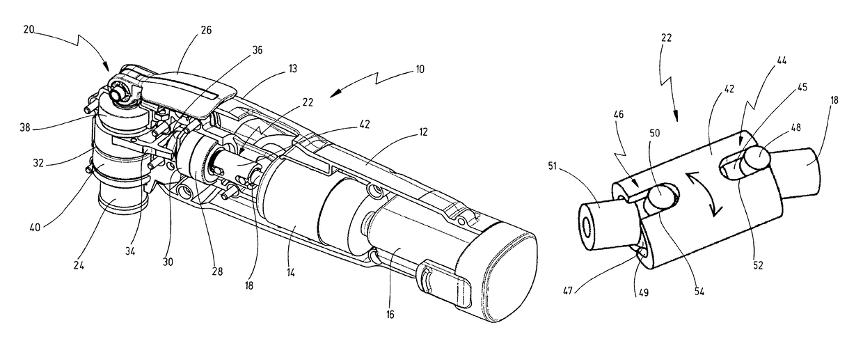
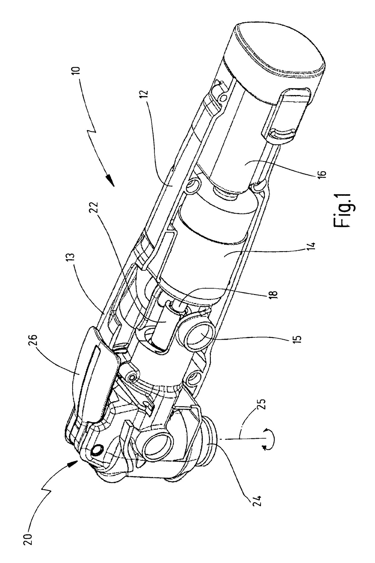
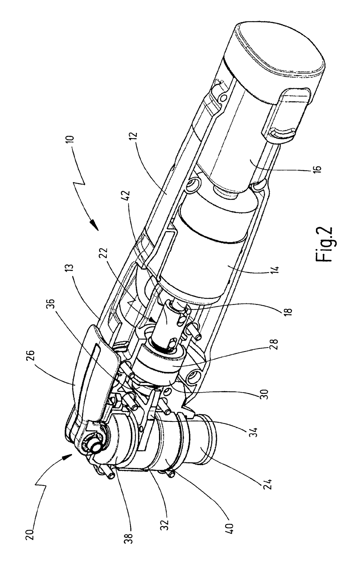
[0068]In FIGS. 1 to 3, a first version of a machine tool according to the invention is designated as a whole by the numeral 10. This is a machine tool 10 driven in oscillation, with a motor housing 12, in which a drive motor 14 is received, and with a gear housing 13, in which a tool drive shaft 24 is received. A rotational movement of the motor shaft 18 is converted via a coupling 22 and an assigned coupling drive 20 into an oscillatingly driven driving movement of the tool drive shaft 24 about its longitudinal axis 25.

[0069]At the outer end of the tool drive shaft 24, which end projects outwards from the housing 12, a tool-holding fixture 43 (FIG. 3) is provided, to which an assigned tool, for example a grinding, cutting or sawing tool, can be fastened by means of a quick-action chucking device (not illustrated) with the aid of a tension lever 26. The tool drive shaft 24 is mounted on the housing 12 with the aid of two bearings 38, 40 (FIGS. 2 and 3).

[0070]The drive motor 14, via ...


PUM

PropertyMeasurementUnit
angleaaaaaaaaaa
dampingaaaaaaaaaa
vibrational decouplingaaaaaaaaaa

Abstract

A motor-driven machine tool has a drive motor, the motor shaft of which is driven in rotation, with a tool drive shaft, which is driven in rotation or in oscillation about its longitudinal axis, and with a coupling drive for converting the rotational movement of the motor shaft into a driving movement of the tool drive shaft. Furthermore, a coupling is provided, which compensates an angular offset or change in position between the motor shaft and tool drive shaft which deviates from an axially parallel or right-angled arrangement of the two shafts.

Description

CROSS REFERENCES TO RELATED APPLICATIONS[0001]This application claims priority from German patent application 10 2013 104 271.6, filed on Apr. 26, 2013. The entire content of this priority application is incorporated herein by reference.BACKGROUND OF THE INVENTION[0002]The invention relates to a motor-driven machine tool with a drive motor, the motor shaft of which is driven in rotation, with a tool drive shaft, which is driven in rotation or in oscillation about its longitudinal axis, and with a coupling drive for converting the rotational movement of the motor shaft into a driving movement of the tool drive shaft.[0003]Machine tools of this type have been known for decades and are used in many different ways particularly as hand-held electric tools. In this context, there are both machines in which the tool drive shaft executes a rotating rotational movement, such as, for example, in drilling machines or angle grinders. Furthermore, in recent years, machines with an oscillating dr...

Claims


Application Information

Patent Timeline
Patent Type & Authority Patents(United States)
IPC IPC(8): B24B23/04F16H25/16B25F5/00B24B23/02B27B19/00B23Q5/027B23D51/16
CPCF16H25/16B24B23/02B24B23/04B25F5/001B27B19/006B23D51/16B23Q5/027Y10T74/18296F16D3/2052B25F5/00
Inventor SEEBAUER, RALF
Owner C & E FEIN GMBH & CO KG
Why Eureka
Try Eureka