
Color electrophoretic display

a color electrophoretic and display technology, applied in the field of display, can solve the problems of severe difficulty in being put into, clustering and agglomeration, and the stability of the electrophoretic display proposed by ota, and achieve the effects of simple process, novel structure, and reliable implementation of color

Active Publication Date: 2009-07-21
ELECTRONICS & TELECOMM RES INST
View PDF11 Cites 8 Cited by
  • Summary
  • Abstract
  • Description
  • Claims
  • Application Information

AI Technical Summary

Benefits of technology

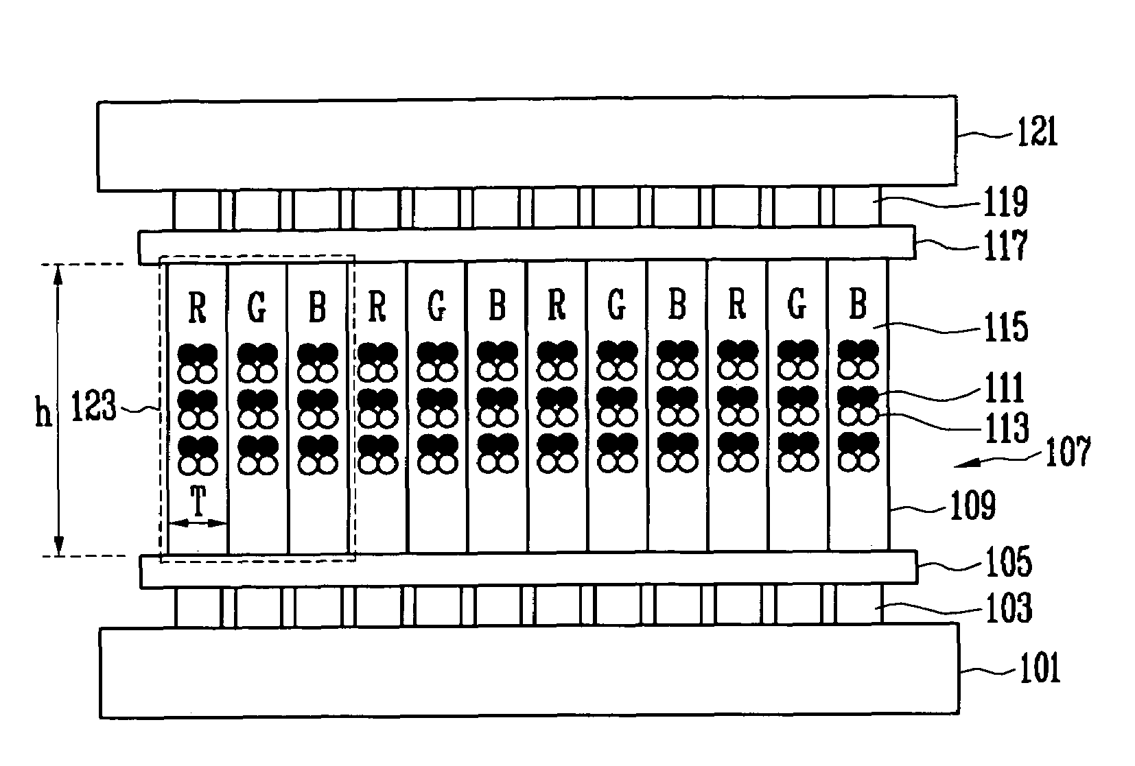
The present invention is a color electrophoretic display with a novel structure and a simple manufacturing process. It includes a lower electrode, a lower electrode protective layer, a photoresist chamber, an electronic ink layer, an upper electrode protective layer, and an upper electrode. The charged particles for displaying a red color, a green color, and a blue color are present within the red, green, and blue electronic inks. The size of the photoresist chamber is equal to or less than the size of the pixel. The dielectric fluid is visually transparent and composed of particles that visually absorb or reflect light. The lower and upper electrodes may have one or three photoresist chambers for injecting the electronic inks. The color electrophoretic display can reliably implement a color using a simple process and a novel structure.

Problems solved by technology

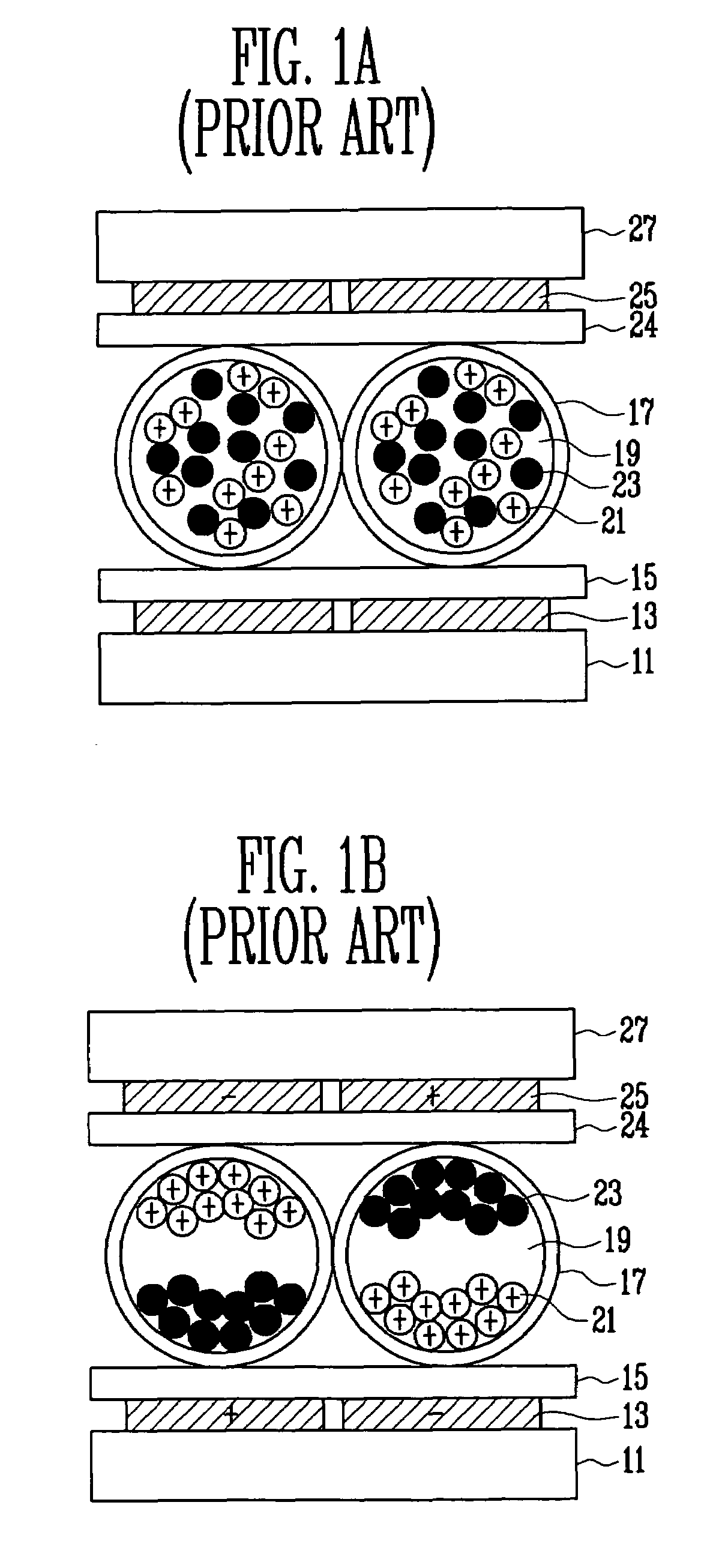
However, the electrophoretic display proposed by Ota had problems in stability.
However, clustering and agglomeration of particles occurred due to the suspension instability according to a time, which were brought to a severe difficulty in being put into a commercial use (see P. Murau and B. Singer, J. Appl. Phys. 49, 1978 p4820).
These problems were not overcome until the late 1990s from 1980s so that the researches could not significantly advance.

Method used


Image

  • Color electrophoretic display
  • Color electrophoretic display
  • Color electrophoretic display

Examples


Embodiment Construction

[0032]The present invention will now be described more fully hereinafter with reference to the accompanying drawings, in which preferred embodiments of the invention are shown. When a layer is described to be formed on another layer or on a substrate, which means that the layer may be formed on the another layer or on the substrate, or a third layer may be interposed between the layer and the another layer or the substrate. In addition, the thickness of layers and regions are exaggerated for clarity in the drawings. Like numbers refer to like elements throughout the specification.

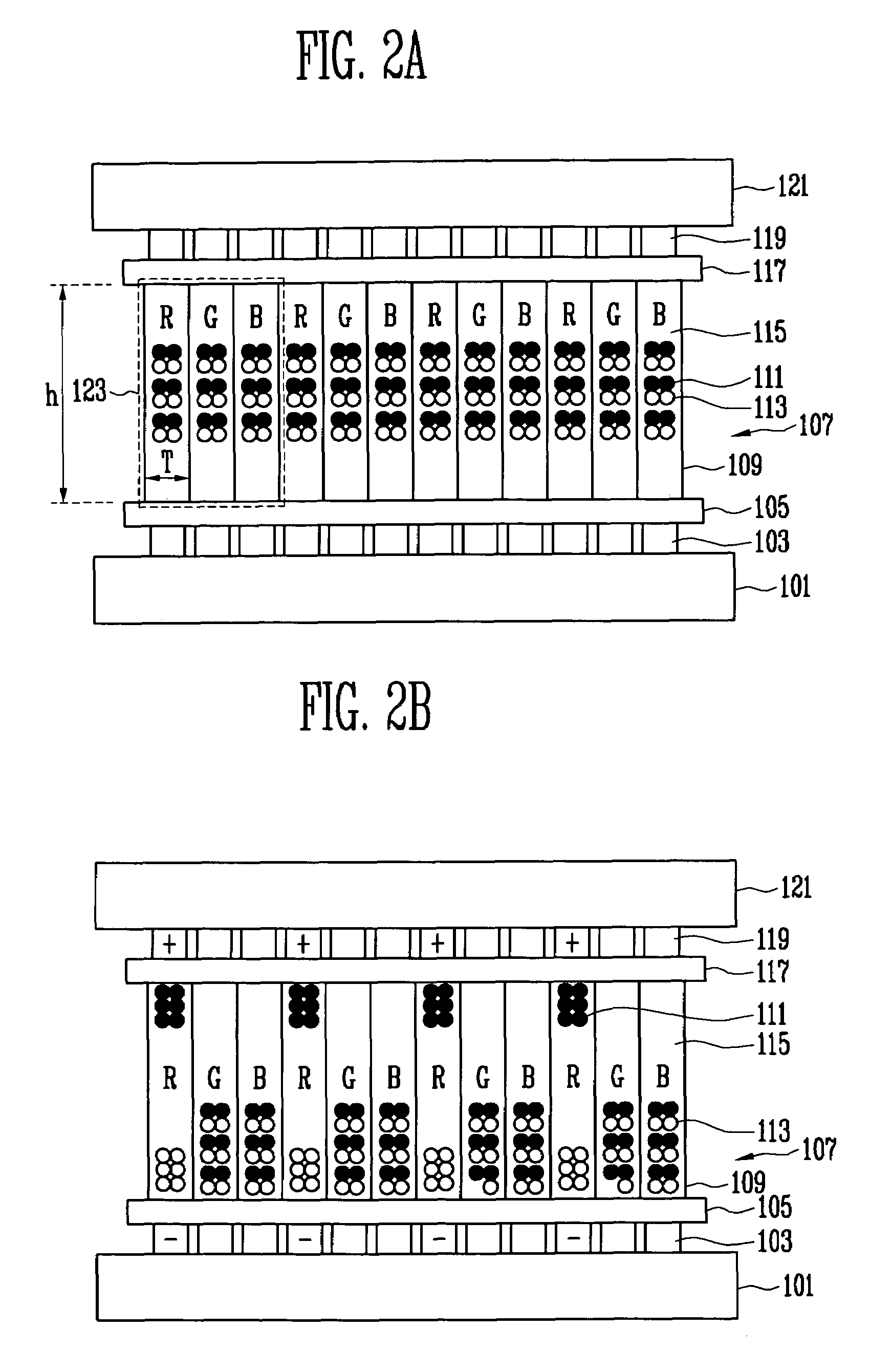
[0033]FIGS. 2A to 2F are partial cross-sectional views illustrating essential components and operating modes of a color electrophoretic display with a photoresist (PR) sheet electronic ink layer structure in accordance with an exemplary embodiment of the present invention.

[0034]First, an essential structure of a color electrophoretic display having a photoresist (PR) sheet electronic ink layer structure wil...


PUM

PropertyMeasurementUnit
widthaaaaaaaaaa
heightaaaaaaaaaa
heightaaaaaaaaaa

Abstract

Provided are a color electrophoretic display and a method of manufacturing the same. The color electrophoretic display includes: a plurality of lower electrodes arranged on a lower layer and disposed with a predetermined interval therebetween; a plurality of first to third photoresist chambers arranged on the plurality of lower electrodes; first to third electronic inks accommodated in the plurality of first to third photoresist chambers respectively, and discriminatively operating to an electric field to independently display red, green, and blue colors; and a plurality of upper electrodes disposed with a predetermined interval therebetween and facing the plurality of lower electrodes with the plurality of first to third photoresist chambers being held therebetween.

Description

CROSS-REFERENCE TO RELATED APPLICATION[0001]This application claims priority to and the benefit of Korean Patent Application No. 2004-105761, filed Dec. 14, 2004, and No. 2005-38558, filed May 9, 2005, the disclosure of which is incorporated herein by reference in its entirety.BACKGROUND[0002]1. Field of the Invention[0003]The present invention relates to a display and more particularly, to a color electrophoretic display (electronic paper) in which red color electronic ink, green color electronic ink, and blue color electronic ink are formed using a photoresist sheet and an exposure process and are sequentially arranged, and a method of manufacturing the same.[0004]2. Discussion of Related Art[0005]An electrophoresis phenomenon means a phenomenon that charged particles move when an electric field is applied between both electrodes. When the electrophoresis occurs within a dielectric fluid, the charged particles move at a velocity determined by a viscous drag, charges, dielectric pr...

Claims


Application Information

Patent Timeline
Patent Type & Authority Patents(United States)
IPC IPC(8): G02B26/00G02F1/167G02F1/1679
CPCG02F1/167G02F2203/34G02F1/1679
Inventor AHN, SEONG DEOKKANG, SEUNG YOULKIM, CHUL AMYOU, IN KYUKIM, GI HEONOH, JI YOUNGBAEK, KYU HASUH, KYUNG SOO
Owner ELECTRONICS & TELECOMM RES INST
Learn More