Multi-building control for demand response power usage control

a technology of demand response and power usage control, applied in the direction of electric devices, process and machine control, instruments, etc., can solve the problem that each such company cannot operate in a vacuum

Inactive Publication Date: 2009-07-21
CONSTELLATION NEWENERGY
View PDF14 Cites 249 Cited by
  • Summary
  • Abstract
  • Description
  • Claims
  • Application Information

AI Technical Summary

Problems solved by technology

However, each such company cannot operate in a vacuum as the amount of power generated must match the amount of power consumed.
Moreover, since the amount of power that can be generated at any point in time is finite, there are cost considerations with requiring (and therefore buying) additional electricity without advanced notice.

Method used


Image

  • Multi-building control for demand response power usage control
  • Multi-building control for demand response power usage control
  • Multi-building control for demand response power usage control

Examples


Embodiment Construction

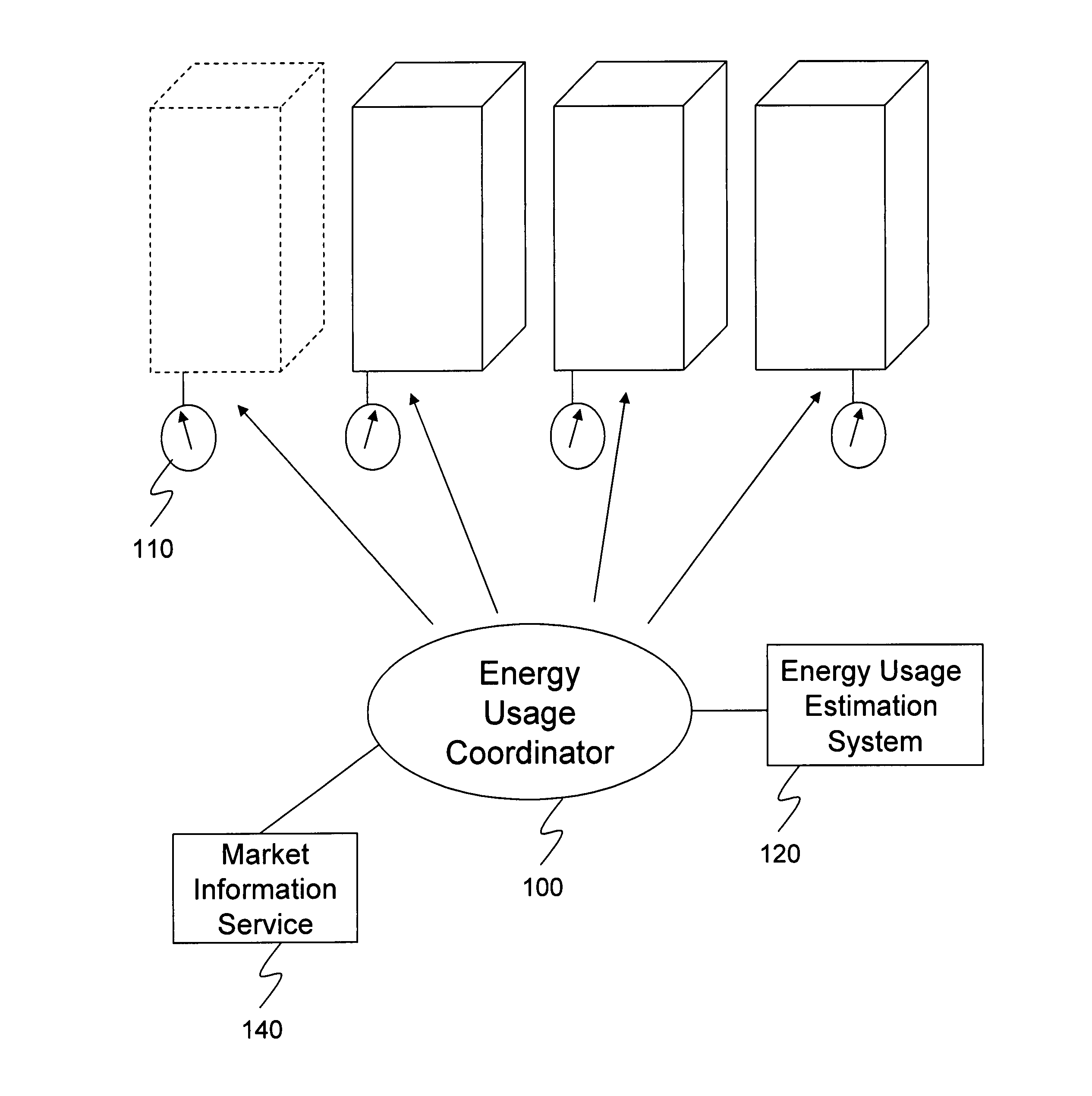
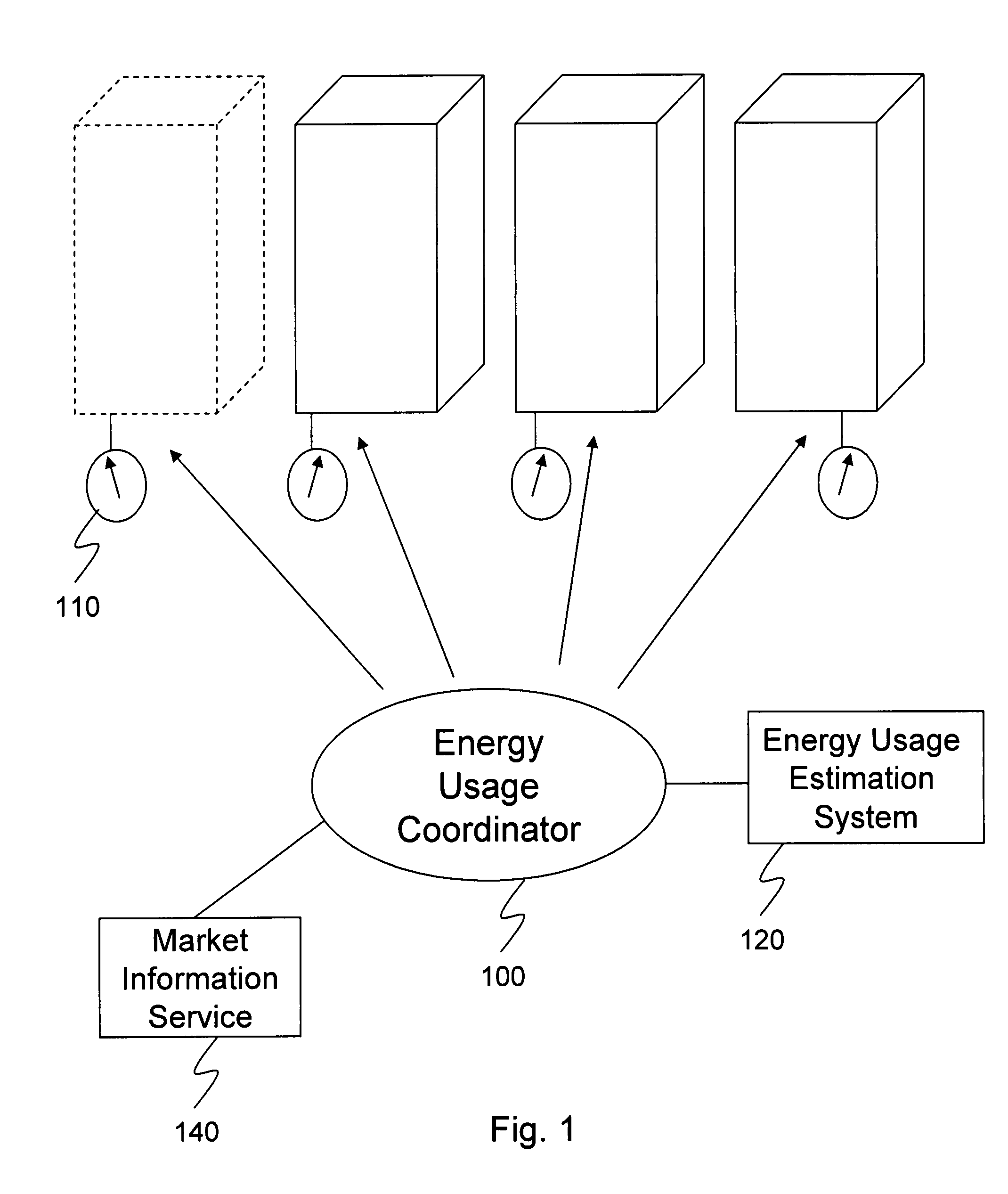
[0013]Turning to FIG. 1, an energy usage coordinator 100 is arranged to control the energy usage of individual buildings of a group (or portfolio) of buildings in one or more load zones. These buildings have all contracted with an energy company which controls (directly or indirectly) the energy usage coordinator. By agreeing to lower energy usage when called upon, the owners or managers of the buildings receive a preferential energy rate from the energy company. Such a preferential rate may be in the form of a fixed rate reduction or a variable rate reduction. Fixed rate reductions include, but are not limited to, a fixed reduced rate for the year, a fixed reduced rate for the month(s) that the building(s) reduced energy usage on demand, a fixed reduced rate for the day(s) that the building(s) reduced energy usage on demand, a fixed rate for the hours that the buildings reduced energy usage on demand. For example, if a building would be able to contract for $0.019 / kW hr for its ene...


PUM


Abstract

An energy usage coordinator controls the energy usage of individual buildings of a group (or portfolio) of buildings in one or more load zones. These buildings have all contracted with an energy company which controls (directly or indirectly) the energy usage coordinator. By agreeing to lower energy usage during times of peak usage (when the energy company may otherwise have to pay very high prices on the spot or short term market), the owners or managers of the buildings receive a preferential energy rate from the energy company. Such a preferential rate may be in the form of a fixed rate reduction or a variable rate reduction. Alternatively, the energy company may determine that the energy is currently selling for twice what its building portfolio has contracted to pay for it so it requests some portion of the portfolio to reduce usage so that it can sell the excess / saved energy in the market.

Description

CROSS REFERENCE TO RELATED APPLICATIONS[0001]The present application is related to the following applications, each of which is incorporated herein by reference: (1) application Ser. No. 11 / 889,633, entitled Multi-Input Building Controller, filed on even date and (2) application Ser. No. 11 / 889,706, entitled Energy Usage Prediction and Control System and Method, filed on even date.FIELD OF INVENTION[0002]The present invention is directed to the field of demand response power usage control and in one embodiment to an interactive, real-time system for controlling the power usage in multiple buildings to achieve power reduction during times of increased power demand.DISCUSSION OF THE BACKGROUND[0003]Electrical power control can be divided into several distinct processes: generation, transmission (including independent service operators), distribution and supply (wholesale and retail). Each of these processes can potentially be provided by a different energy company or service provider....

Claims


Application Information

Patent Timeline
Patent Type & Authority Patents(United States)
IPC IPC(8): G05D3/12G05D11/00G05D5/00G05D9/00G05D17/00G01R21/00G01R21/07G06F1/00G06F17/30
CPCG06Q10/06312H02J3/14H02J9/005H02J2003/143H02J2003/146Y04S20/242Y02B70/3233Y02B70/3266Y04S20/222Y04S20/224Y04S20/225Y02B70/3225H02J2310/64H02J2310/14Y02B70/30Y04S20/20Y04S50/10
Inventor RICHARD, AMYKELLY-DETWILER, PETERFRANZ, JOSEPH
Owner CONSTELLATION NEWENERGY
Why Eureka
Try Eureka