Network system
a network system and network technology, applied in the field of network systems, can solve the problems of difficult to realize efficient management in terms of energy generation, distribution and use, and achieve the effects of reducing energy consumption cost and power consumption, effective management of energy sources, and efficient production, use, and storag
- Summary
- Abstract
- Description
- Claims
- Application Information
AI Technical Summary
Benefits of technology
Problems solved by technology
Method used
Image
Examples
first embodiment
[0201]FIG. 4 is a view showing the communication structure of two components that constitute the network system according to a FIG. 5 is a block diagram showing the detailed configuration of a communication device that constitutes a communication unit.
[0202]Referring to FIGS. 2, 4 and 5, first and second component 61 and 62 that constitute the network system may perform wired or wireless communication by means of a communication unit 50. The first and second components 61 and 62 may perform unidirectional or bidirectional communication.
[0203]In a case where the two components 61 and 62 perform wired communication, the communication unit 50 may be a simple communication line or power line communication means. It will be apparent that the power line communication means may include communicators (e.g., a modem or the like) respectively connected to the two components.
[0204]In a case where the two components 61 and 62 perform wireless communication, the communication unit 50 may includ...
second embodiment
[0238]FIG. 7 is a view showing a communication performing process between a specific component and a communication device according to a
[0239]Hereinafter, for convenience of illustration, a communication performing process between the second component 62 and the second communicator 52 will be described as an example. A communication performing process between the first component 61 and the first communicator 51 may be identically applied to that between the second component 62 and the second communicator 62.
[0240]Referring to FIGS. 5 and 7, the second communicator 52 receives a message from the first communicator 51. The second communicator 52 may receive a message in real time or by periods without transmitting a request for the message to the first communicator 51, or may receive a message as a response for the request for the message to the first communicator 51. Alternatively, the second communicator 52 may receive a message by requesting information to the first communicator 51...
third embodiment
[0276]FIG. 8 is a view showing the communication structure of components that constitute the network system according to a FIG. 9 is a block diagram showing the detailed configuration of a first component in FIG. 8.
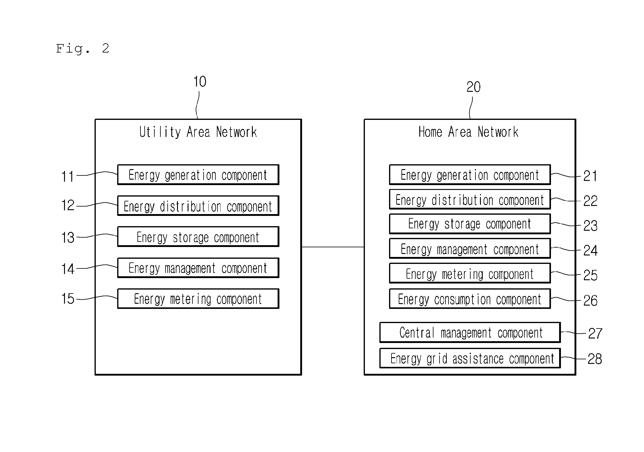
[0277]Referring to FIGS. 8 and 9, a first component 70 may communicate with second to fifth components 82, 83, 84 and 85. Hereinafter, it will be described as an example that the first component 70 is a central management component (home server), the second and third components 82 and 83 are energy consumption components (electric home appliances), the fourth component 84 is an energy metering component (smart meter), and the fifth component 85 is a component that constitutes the UAN. The components may communicate with each other by means of a communication unit. In the network system illustrated in FIG. 8, each of the components is directly connected to the first component 70 to communicate with the first component 70. However, in a case where each of the components 82...
PUM
 Abstract
Description
Claims
Application Information
 - R&D
- Intellectual Property
- Life Sciences
- Materials
- Tech Scout
- Unparalleled Data Quality
- Higher Quality Content
- 60% Fewer Hallucinations
Browse by: Latest US Patents, China's latest patents, Technical Efficacy Thesaurus, Application Domain, Technology Topic, Popular Technical Reports.
© 2025 PatSnap. All rights reserved.Legal|Privacy policy|Modern Slavery Act Transparency Statement|Sitemap|About US| Contact US: help@patsnap.com


