Apparatus for production of metal chloride

Inactive Publication Date: 2007-08-02
TOHO TITANIUM CO LTD
View PDF3 Cites 25 Cited by
  • Summary
  • Abstract
  • Description
  • Claims
  • Application Information

AI Technical Summary

Benefits of technology

[0011] An object of the invention is to provide an apparatus for production of metal chloride in which a durability of the distributor for

Problems solved by technology

In the distributor unit of the nozzle type configuration, some impurities are frequently precipitated near nozzle openings and as a result the chlorine gas is non-uniformly dispersed, and the chlorination reaction between the chlorine gas and the raw material cannot be performed sufficiently.
However, silica pebbles employed as a bed materials packed in the distributor is often crushed, fined, corroded and worn due to the high-temperature chlorine gas during the long term operations, and the dispersion state of the chlorine gas in the fluidized bed becomes getting worse.
In addition, a cylindrical vessel wall keeping the bed configuration is arranged on the distributor, and also may be corroded and worn during the long term operation in the chlorinati

Method used


Image

  • Apparatus for production of metal chloride
  • Apparatus for production of metal chloride
  • Apparatus for production of metal chloride

Examples


example 1

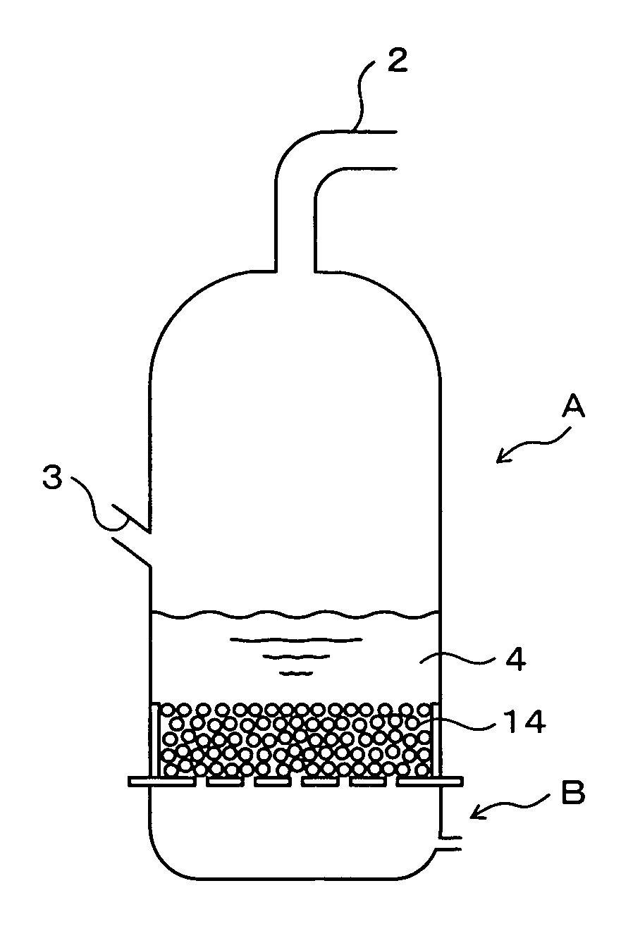
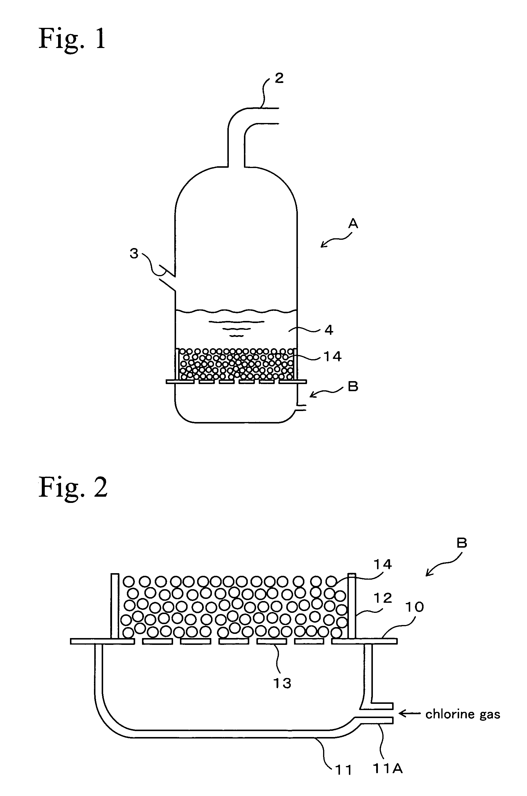
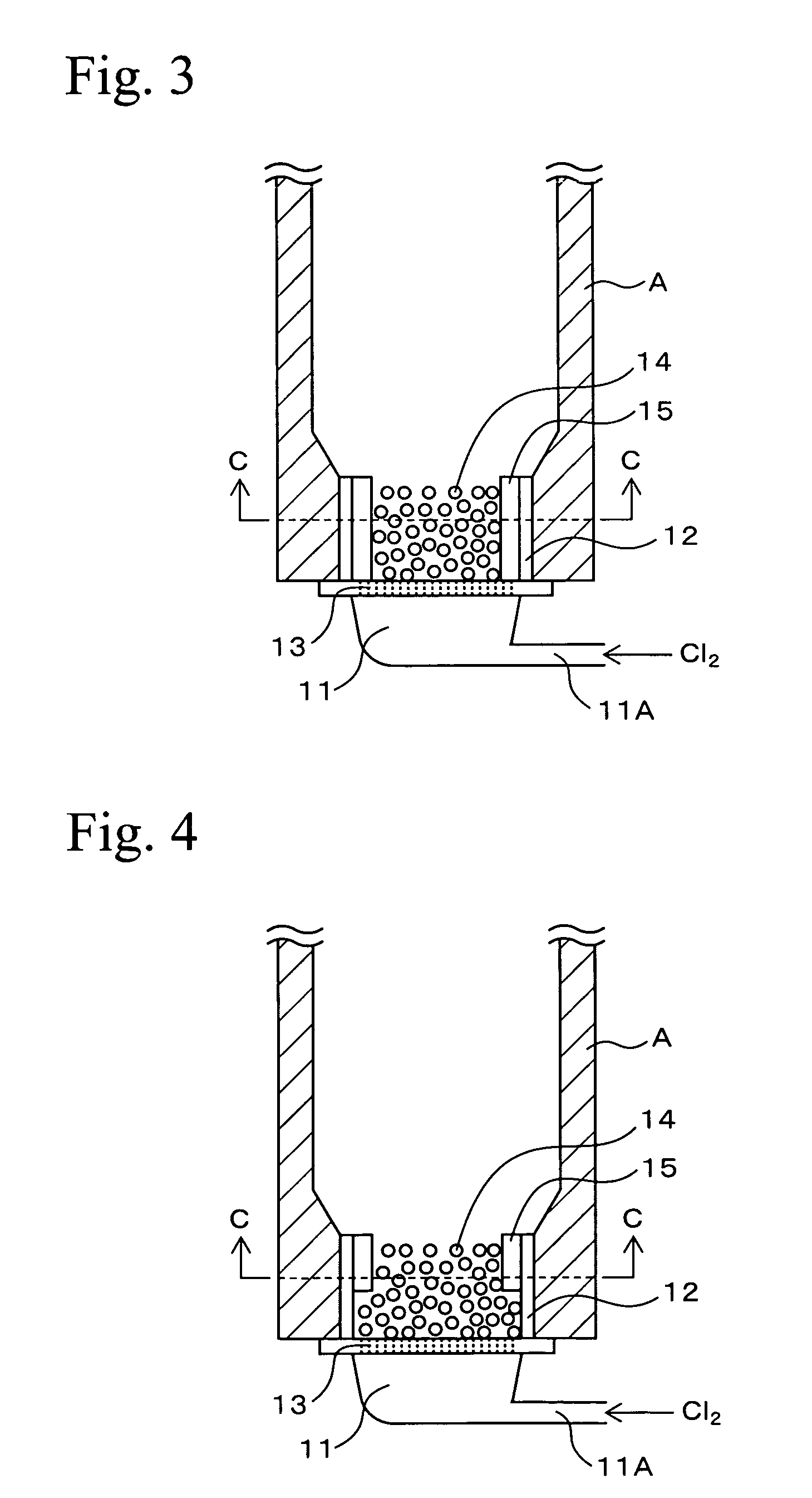
[0084] Ceramic particles having equivalent diameters from 10 to 50 mm comprising fused silica having a density of 2.7 g / cm3 (purity: 99.8%, porosity: not more than 0.1%) were uniformly arranged on the porous plate 13 of the distributor B shown in FIG. 3 so as to fill the inside of the vessel wall 12. The inner space surrounded by the vessel wall 12 was filled until its top to form the packed bed having a bulk density of 1.3 g / cm3. The distributor having this packed bed was attached to the chlorination furnace, and the chlorination furnace was operated for 18 months. After terminating the operation, the packed bed of the distributor was disassembled for examination. As a result, evidence of the carry-over loss of the surface portion of the fused silica layer was observed; however, the overall initial condition was completely maintained. In addition, there was no alarm sounded due to unreacted chlorine gas detection in the exhaust gas from the chlorination furnace.

example 2

[0085] Using the apparatus shown in FIG. 3, titanium ore was chlorinated under the conditions mentioned above to produce titanium tetrachloride. During the chlorination, after titanium ore and coke were filled on the dispersion means to form a layer of these raw materials, a predetermined amount of chlorine gas was supplied to produce titanium tetrachloride. The temperature of the wall of the chlorination furnace body was measured at 3, 6, 9, and 12 months after starting of production of titanium tetrachloride; however, noticeable temperature increase was not observed. This fact shows that corrosion and wear of the inner wall bricks of the chlorination furnace were not seriously proceeded. After 18 months from starting of the operation, the chlorination was terminated and the inner wall of the chlorination furnace body was observed; noticeable damage was not observed. Therefore, the partial maintenance and repairing were conducted and the furnace was also reused in the subsequent op...


PUM

PropertyMeasurementUnit
Diameteraaaaaaaaaa
Densityaaaaaaaaaa
Porosityaaaaaaaaaa

Abstract

Porous plate 13 is disposed between wind box 11 of dispersion board B and cylindrical vessel wall 12. Filling layer 14 of a structure packed with ceramic particles such as those of fused silica is disposed on the porous plate 13 so as to fill the inside of the cylindrical vessel wall. The filling layer 14 is composed of ceramic particles, so that the corrosion wear by chlorine gas can be inhibited and the durability thereof enhanced. Furthermore, a chlorine resistant member is disposed in a form so as to adhere to the internal surface of the cylindrical vessel wall 12, so that the corrosion wear by chlorine gas of the cylindrical vessel wall 12 can also be effectively inhibited. As a result, damage to the internal wall of the chlorination furnace can be minimized, and the state of allowing chlorine gas to be uniformly dispersed and supplied to fluidized bed 4 containing titanium ore and coke can be maintained for prolonged periods.

Description

TECHNICAL FIELD [0001] The present invention relates to a production apparatus in which raw materials, such as metal oxide or metal and chlorine gas, are contacted to perform chlorination in a chlorination furnace, and in particular, relates to a structure of a distributor arranged in a chlorination furnace which is a production device for metal chlorides. BACKGROUND ART [0002] Titanium tetrachloride, which is one of the metal chlorides, is widely employed for producing titanium sponge or titanium oxide, and electronic materials. Titanium tetrachloride is efficiently produced by using the above-described chlorination furnace. [0003] In such a chlorination furnace for production of titanium tetrachloride, a distributor, which disperses chlorine gas, is arranged at the bottom part of the apparatus. Titanium ore and coke, which are raw materials of titanium tetrachloride, are supplied from the side opening of the chlorination furnace into a fluidized bed formed above the distributor. C...

Claims


Application Information

Patent Timeline
IPC IPC(8): B01J8/00B01J8/18B01J19/02C01B9/02C01B33/107C01G1/06C01G23/02C01G35/02
CPCB01J8/18B01J19/02B01J2208/00849B01J2219/0263C01G35/02C01B33/1071C01G1/06C01G23/02C01G23/022C01B9/02
Inventor FUKASAWA, EIICHIARAI, FUMITOYAMAMOTO, MASASHI
Owner TOHO TITANIUM CO LTD
Why Eureka
Try Eureka