Energy optimization system

a technology of energy optimization and energy generation, applied in the integration of power network operation systems, instruments, base element modifications, etc., can solve the problems of increasing transmission and distribution costs to consumers, inefficient energy available at the location of operation, and many significant hurdles in the wind energy industry

Active Publication Date: 2011-08-11
STALKER JAMES R
View PDF21 Cites 8 Cited by
  • Summary
  • Abstract
  • Description
  • Claims
  • Application Information

AI Technical Summary

Problems solved by technology

When energy is transported from the generation facility to the location of operation, there are additional transmission and distribution costs to the consumer, in addition to the costs associated with the energy losses in transmission.
Depending on the required transmission distance, such energy available at the location of operation may be considered more (large distances) or less (short distances) inefficient.
Additionally, the wind energy industry faces many significant hurdles before such national goal can become reality.
One of those known hurdles results from utility scale wind resource locations usually being much farther away from where the load centers (locations of operation) are located.
This need is proven to be a severe bottleneck for wind project growth as utilities are wary of the unsteady nature of wind energy.
This situation is not conducive to aggressive wind project development growth in the U.S. and around the world.
However, the existing approach does not address the problem resulting from the f...

Method used


Image

  • Energy optimization system
  • Energy optimization system
  • Energy optimization system

Examples


Embodiment Construction

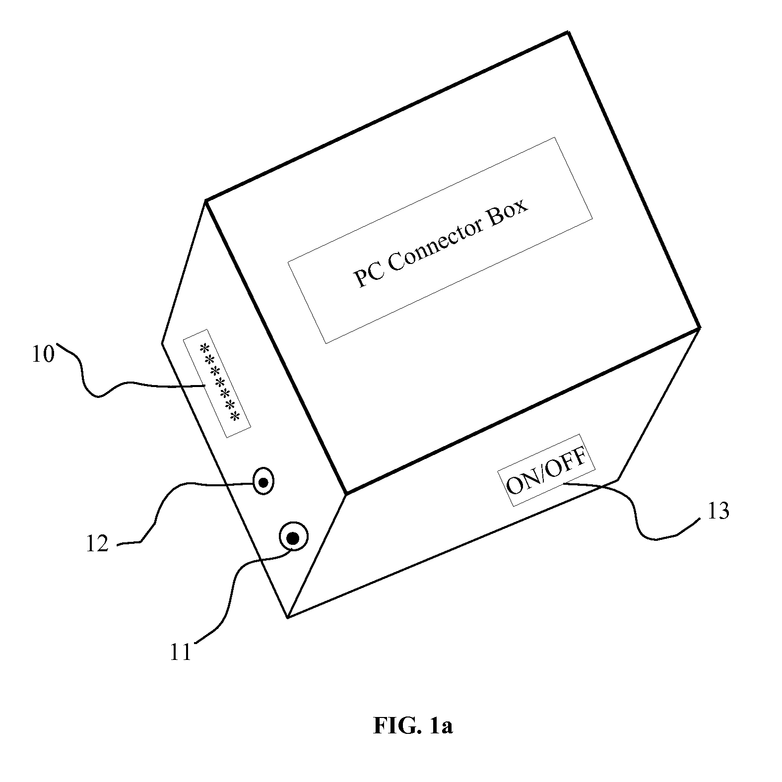
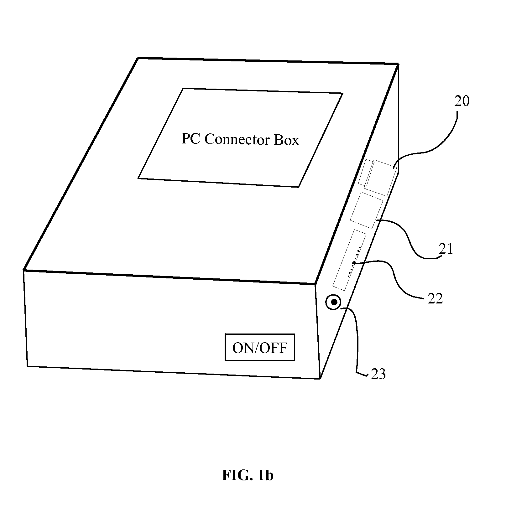
[0033]The traditional personal computer (PC) is strategically separated into two sets of parts. The first set of parts is the PC Connector Box, shown in FIGS. 1 (a, b, and c). The main function of the PC Connector Box is to provide the functionality to connect the PC user to the PC box (the second set of parts). Four aspects of the PC Connector Box are shown FIG. 1a. In FIG. 1a, a monitor / VGA port (10), a keyboard port (11), a mouse port (12), and an on / off power button (13) are shown. In FIG. 1b, an ethernet port (20), a universal serial bus (USB) port (21), a printer port (22), and a portable / chargeable battery plug-in (23) are shown. In FIG. 1c, the case (30) to hold these parts together, a miniature motherboard (31), a miniature central processing unit (CPU) (32), and a basic input / output system (BIOS) read-only-memory (ROM) location where lean operating system code resides (33). This PC Connector Box will be able to be connected to the internet, without requiring the usual moth...


PUM


Abstract

A system with three distinct but integral aspects for an effective energy optimization solution is disclosed. First, the system comprises a Smart Energy Load Center (SELC) adjacent to an energy generation facility (e.g., a wind farm) to limit or to entirely eliminate energy losses in transit and to reduce transmission and distribution infrastructure costs, and to eliminate energy handling costs reflected in relatively higher retail energy rates, compared to lower wholesale energy rates. Second, the system comprises methods to split existing energy consuming gadgets/gizmos (e.g., personal computers—PCs) into two sets of parts and moves the bigger set of the parts to the SELC without compromising the original functionality of the gadgets/gizmos. Thirdly, the system utilizes the material reduction and increased design features and cost savings yielded by the economies of scale offered by PCs residing at the SELC (Remote PC Warehouse) and harnesses the residual energy contained in the digital information.

Description

CROSS REFERENCES TO RELATED APPLICATIONS[0001]This application is related to and claims priority to a provisional patent application submitted by James R. Stalker, dated Nov. 24, 2009 (App No. 61 / 263,911).STATEMENT REGARDING FEDERALLY SPONSORED R&D[0002]Not Applicable.NAMES OF PARTIES INVOLVED IN THIS INVENTION[0003]James R. Stalker is the sole inventor of this invention.BACKGROUND OF THE INVENTION[0004]1. Field of the Invention[0005]This invention is related to the field of energy generation from renewable or conventional energy fuel sources and energy consumption in an efficient and optimized manner.[0006]2. Description of the Prior Art[0007]Where energy is generated and where it is consumed are often two different geographic locations today. In other words, consumers expect to use gadgets and gizmos where they live in their homes or where they work at businesses or at places where they manufacture goods and other perishable (e.g., foods) or non-perishable consumer products. The f...

Claims


Application Information

Patent Timeline
IPC IPC(8): H02J11/00
CPCH02J3/008H02J3/14H02J3/383H02J3/386H02J2003/146H02J3/382Y02E10/563Y02E10/763Y04S20/222Y04S20/224Y04S50/10Y02B70/3225H02J2310/64H02J2300/28H02J2300/20H02J2300/24H02J3/381Y02E10/56Y02E10/76
Inventor STALKER, JAMES R.
Owner STALKER JAMES R
Why Eureka
Try Eureka