Eureka AIR delivers breakthrough ideas for toughest innovation challenges, trusted by R&D personnel around the world.

Piezo-resonance igniter and ignition method for propellant liquid rocket engine

a technology of igniter and propellant liquid, which is applied in the direction of machines/engines, marine propulsion, vessel construction, etc., can solve the problems of spark production stoppage, reduce the pressure drop across the resonance system, and simplify the control and operation of the rocket engine.

Active Publication Date: 2009-07-28
AEROJET ROCKETDYNE OF DE
View PDF83 Cites 14 Cited by
  • Summary
  • Abstract
  • Description
  • Claims
  • Application Information

AI Technical Summary

Benefits of technology

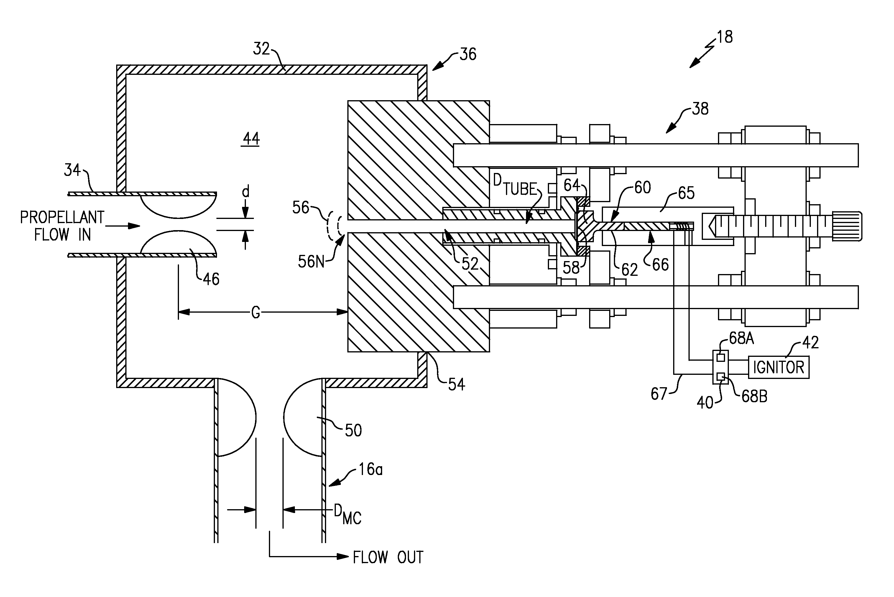
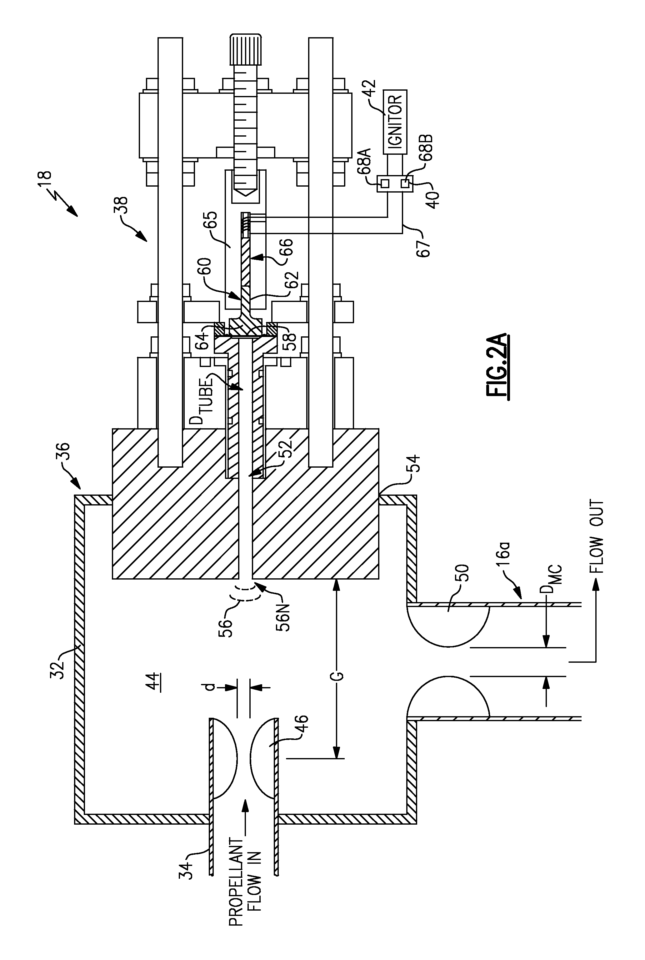
[0005]The ignition system according to the present invention generally includes a resonance system in communication with a propellant system, a piezoelectric system, and an electrical conditioning system to power an igniter and ignite a propellant flow. The resonance system is in communication with the piezoelectric system through a gas resonance tube which is sealed with a force transmission diaphragm. A force transfer member increases the surface area in contact with the force transmission diaphragm to react pressure loads from an oscillating flow within the resonance tube. The sizing of the diaphragm allows the resonance pressure pulses to act over a relatively large effective area to increase a net force output for a given resonance gas resonance tube diameter and supply pressure.
[0007]Since the spark energy production is driven by the resonance of the propellant flow, a passive auto-ignition system is provided. When the propellant valves are opened, flow through the resonance system is such that resonance occurs and spark energy is generated. Once ignition occurs, the resultant backpressure in the combustion chamber reduces the pressure drop across the resonance system and “detunes” the resonance phenomena, such that spark production stops. Furthermore, should the engine flame out causing combustion chamber pressure to drop again, spark production automatically resumes as long as the propellant valves remain open. Control and operation of the rocket engine is considerably simplified through elimination of the heretofore necessity of an electrical power supply and separate switching commands and monitoring of the ignition system such that the otherwise typical uncertainties in setting spark timing and duration are obviated. Significant advantages are thereby provided for distributed multi-thruster systems, such as an Attitude Control System (ACS), where the characteristics of a conventional ignition system are multiplied by a significant number of thrusters.
[0008]The present invention therefore provides an uncomplicated, lightweight passive auto ignition system with restart capability that eliminates separate spark exciter electronics and switching command systems.

Problems solved by technology

Once ignition occurs, the resultant backpressure in the combustion chamber reduces the pressure drop across the resonance system and “detunes” the resonance phenomena, such that spark production stops.

Method used


Image

  • Piezo-resonance igniter and ignition method for propellant liquid rocket engine
  • Piezo-resonance igniter and ignition method for propellant liquid rocket engine
  • Piezo-resonance igniter and ignition method for propellant liquid rocket engine

Examples


Embodiment Construction

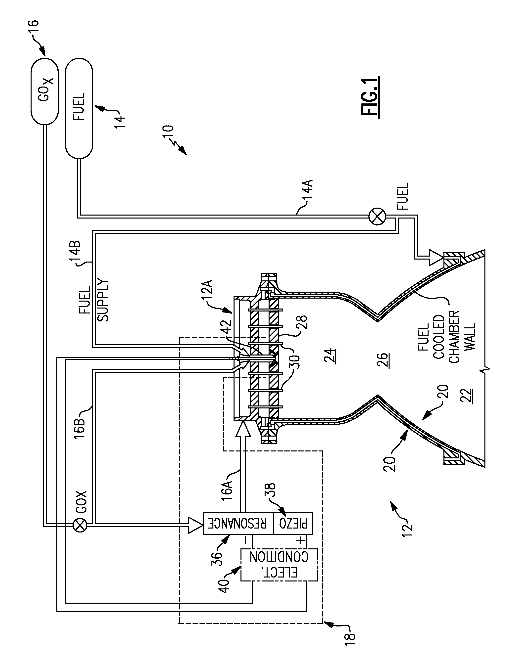
[0016]FIG. 1 illustrates a general schematic view of a rocket engine 10. The engine 10 generally includes a thrust chamber assembly 12, a fuel system 14, an oxidizer system 16 and an ignition system 18. The fuel system 14 and the oxidizer system 16 preferably provide a gaseous propellant system of the rocket engine 10, however, other propellant systems such as liquid will also be usable with the present invention.

[0017]A combustion chamber wall 20 about a thrust axis A defines the nozzle assembly 12. The combustion chamber wall 20 defines a thrust chamber 22, a combustion chamber 24 upstream of the thrust chamber 22, and a combustion chamber throat 26 therebetween. The thrust chamber assembly 12 includes an injector 12A with an injector face 28 which contains a multitude of fuel / oxidizer injector elements 30 (shown somewhat schematically) which receive fuel which passes first through the fuel cooled combustion chamber wall 20 fed via fuel supply line 14a of the fuel system 14 and an...


PUM


Abstract

An ignition system for a rocket engine utilizes the pressure energy in a propellant flow. The propellant flow generates an oscillating pressure force in a resonance system which is then transmitted to a piezoelectric system. The electrical pulses are utilized to generate a spark in an igniter system spark gap, resulting in ignition. Since the spark energy production is driven by the resonance of the propellant flow, a fully passive auto-ignition system is provided. Once ignition occurs, the resultant backpressure in the combustion chamber “detunes” the resonance phenomena and spark production stops. Furthermore, should the engine flame out, spark production would automatically resume as the propellant valves remain open thereby providing relight capability.

Description

BACKGROUND OF THE INVENTION[0001]The present invention relates to a piezo-resonance igniter system for passive auto ignition of a rocket engine, and more particularly to a method which utilizes the pressure energy in the propellants themselves to excite piezoelectric crystals such that high voltage electrical pulses are created to generate a spark in an igniter system.[0002]Various conventional ignition systems have been used for ignition of a propellant mixture in a combustion chamber of a rocket engine. These ignition systems generally employed a spark induced by an electrical current from a source of electricity and a control for sensing when to supply and discontinue the spark. These conventional systems, although effective, tend to be relatively complex, heavy, and may not provide restart capability.[0003]With the increasing need for safe storable propellant systems such as Gaseous Oxygen (GOx) and Methane combinations, an uncomplicated fully passive auto ignition system is des...

Claims


Application Information

Patent Timeline
Patent Type & Authority Patents(United States)
IPC IPC(8): F02G1/00
CPCF02K9/95F02P15/003F02P3/12
Inventor HORN, MARK D.WALCZUK, THOMAS M.
Owner AEROJET ROCKETDYNE OF DE
Why Eureka
Eureka Blog
Learn More