Variable orifice combustor

a combustor and variable orifice technology, applied in the direction of combustion types, combustion processes, lighting and heating apparatus, etc., can solve the problems of incomplete reaction, non-paralleled force, and inability to control

Active Publication Date: 2009-07-28
STRIJDOM MR JOHANNES GERHARDUS 11 ASSIGNMENT +3
View PDF20 Cites 11 Cited by
  • Summary
  • Abstract
  • Description
  • Claims
  • Application Information

AI Technical Summary

Benefits of technology

[0008]U.S. Pat. No. 4,708,637 does not present means for regulating injection velocity pressures as is the case with the present invention. A minimal fluctuation of input flows and pressures, when involving this disclosure, creates inadequate mixing causing resultant forces that are non-parallel to jet direction. This in turn minimizes the development of kinetic energy in discharged combusted gases that consequently affects effective convection. The absence of the ability to control injection velocity pressures is detrimental for staged combustion especially at lower operating temperatures thus causing incomplete reaction and overheating while in larger units combustion takes place more radiantly thus creating nitrous oxides because of the lack of vortex formation.

Problems solved by technology

A minimal fluctuation of input flows and pressures, when involving this disclosure, creates inadequate mixing causing resultant forces that are non-parallel to jet direction.
The absence of the ability to control injection velocity pressures is detrimental for staged combustion especially at lower operating temperatures thus causing incomplete reaction and overheating while in larger units combustion takes place more radiantly thus creating nitrous oxides because of the lack of vortex formation.

Method used


Image

  • Variable orifice combustor
  • Variable orifice combustor
  • Variable orifice combustor

Examples


Embodiment Construction

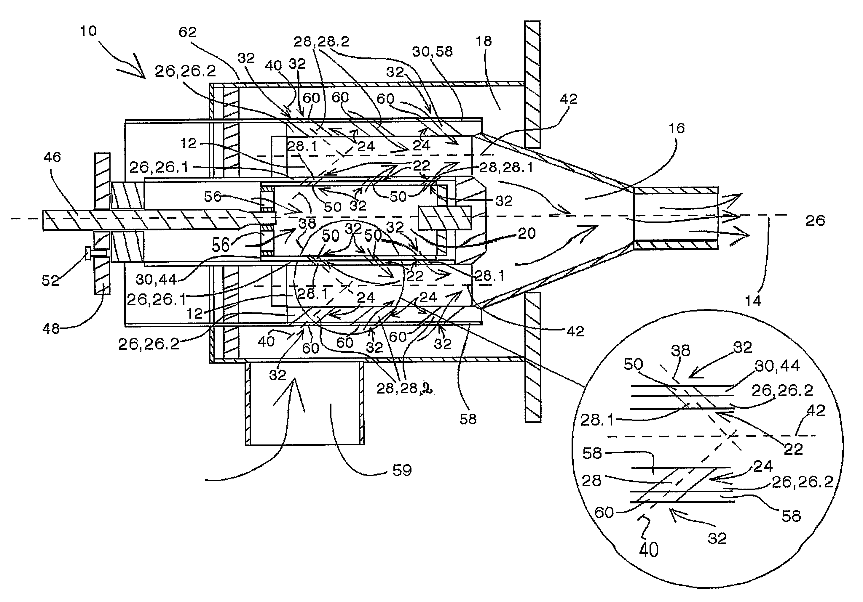
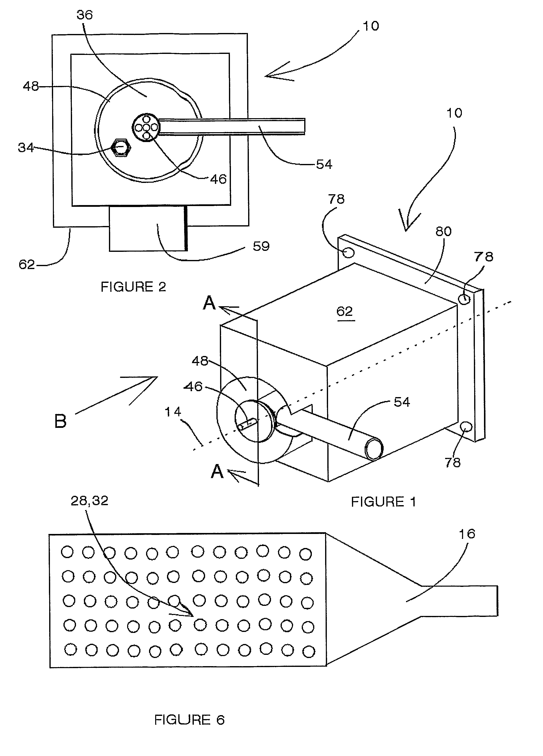
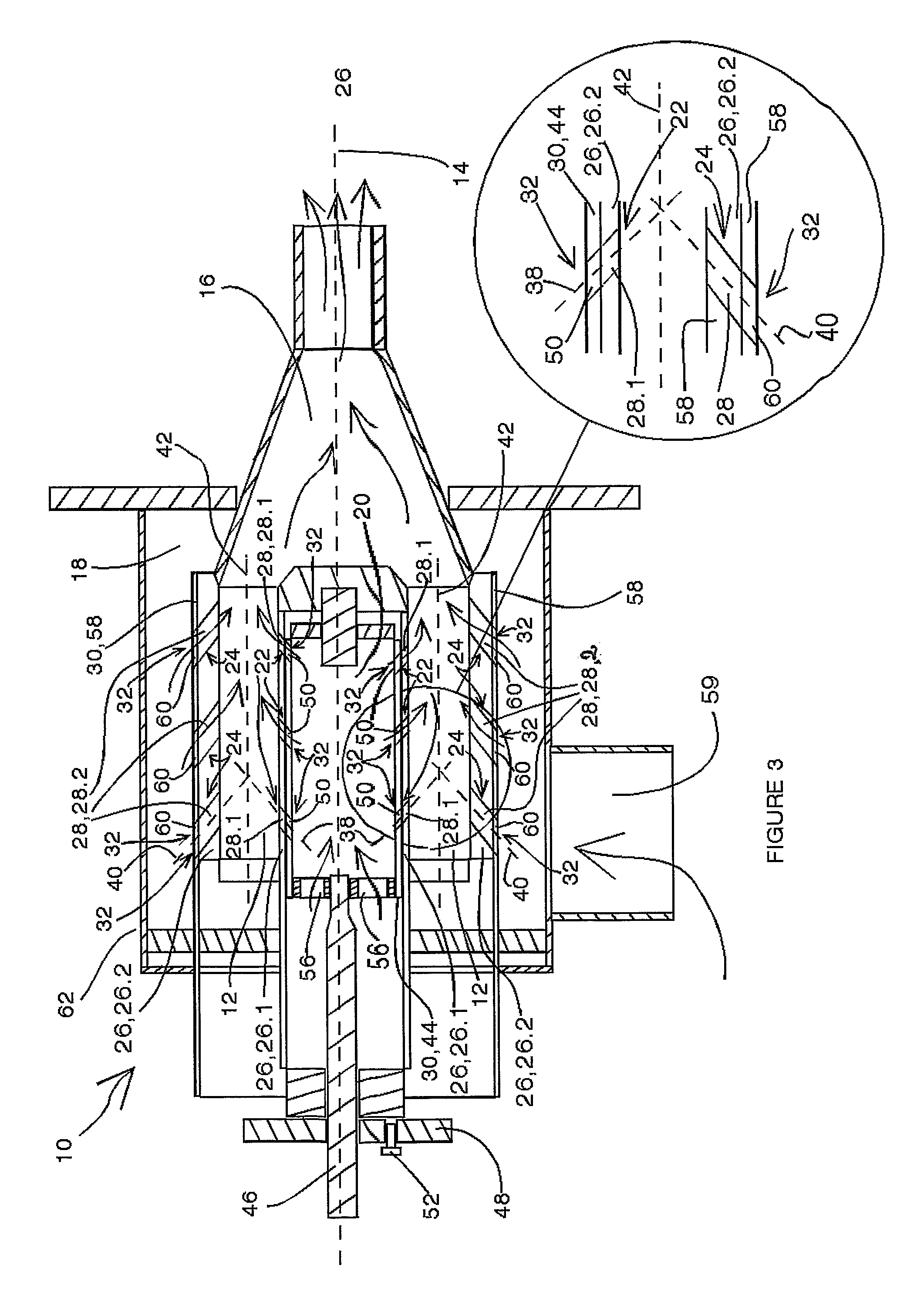
[0016]Referring to the drawings a variable orifice combustor in the form of a combustor unit is generally indicated by reference numeral 10.

[0017]The combustor 10 comprises a combustion chamber 12 extending regularly about a central axis 14 and ending in a progressively constricted combusted medium discharge in the form a discharge nozzle 16 while charging of the chamber 12 takes place from combustion fuel and air supply dispositions in the form of an air charging chamber 18 and a fuel charging chamber 20 via combustion medium orifice arrays in the form of a fuel charging orifice array 22 and an air charging orifice array 24 formed in facing longitudinal walls 26 of the chamber and of which arrays 22, 24 the cross sectional sizes of the orifices 28 are adjustable by means of an adjustment mechanism including displaceably mounted orificed covering means 30 being formed with covering means orifice arrays 32 in number and size matching those of the relevant medium orifice array 22, 24 ...


PUM


Abstract

A variable orifice combustor unit 10 comprises an annular combustion chamber 12 extending about a central axis 14 and ending in a discharge nozzle 16. Charging of the chamber 12 takes place from combustion fuel and air supply chambers 18 and 20 via a fuel charging orifice array 22 and an air charging orifice array 24. The orifices 28.1, 28.2 of the orifice arrays 22, 24 are positioned and slanted at the same forward angle in the direction of the nozzle 16 to the effect of their central axes 38, 40 cutting along the longitudinal centre of the combustion chamber 12. The cross sectional sizes of the orifices 28 are adjustable by means of an orificed displaceably mounted cyndrically shaped covering body 44 for the fuel charging side and an orificed cylindrical body 58 for the air charging side both being displaceable in the direction of the axis 12.

Description

CROSS-REFERENCE TO RELATED APPLICATIONS[0001]This application claims priority to PCT / ZA2005 / 000059 filed on Apr. 19, 2005, and ZA2004 / 2919 filed Apr. 19, 2004, the contents of which are fully incorporated by reference.STATEMENT REGARDING FEDERALLY SPONSORED RESEARCH OR DEVELOPMENT[0002]Not applicableREFERENCE TO MICROFICHE APPENDIX[0003]Not applicableBACKGROUND TO THE INVENTION[0004]The use of directly fired combustors for heating purposes even at high temperatures up to in the order of 1000 degrees C. is common in the industry. The heat loss experienced by conventional directly fired combustors is generally directly proportional to their operating temperatures resulting in a high temperature causing a substantial loss of heat in turn implying an increased fuel consumption. Very high temperatures also produce fatigue in the materials used in the surroundings of a combustor. A lower process temperature requires an intensification of the speed at which convection heat reaches its inte...

Claims


Application Information

Patent Timeline
Patent Type & Authority Patents(United States)
IPC IPC(8): F23N1/02F23C6/04F23C7/00F23D14/20F23D14/60
CPCF23C7/008F23N1/027F23D14/60F23D14/20F23C2900/03005
Inventor MORSNER, JOHANN CARL
Owner STRIJDOM MR JOHANNES GERHARDUS 11 ASSIGNMENT
Why Eureka
Try Eureka