Counter current mixing reactor

a technology of mixing reactor and counter current, which is applied in the direction of flow mixer, chemical/physical/physical-chemical stationary reactor, bulk chemical production, etc., can solve the problems of eventual blockage of the reactor and the restriction of flow, so as to reduce the potential for mixing, avoid premixing or stagnation, and reduce the effect of pipework blockag

Active Publication Date: 2009-07-28
PROMETHEAN PARTICLES
View PDF11 Cites 19 Cited by
  • Summary
  • Abstract
  • Description
  • Claims
  • Application Information

AI Technical Summary

Benefits of technology

[0010]The principle advantage of the invention is that the mixing reactor exploits the differences in density between the fluids to avoid premixing or stagnation thus minimising blockage of the pipework or reactor. This is the main problem with other reactor configurations and is caused by back mixing in the inlets to the mixer. This causes particulate formation upstream of the mixing point and consequent flow restriction and eventual blockage of the reactor. The invention eliminates this by removing the potential for mixing to occur in the inlets of the reactor.
[0011]It will be appreciated that references to ‘differing densities’ include differences in the order of greater than 5%, 10%, 20%, 50%, 100%, 500% or ranges between any of these values.
[0012]In one embodiment of the invention, there is provided a counter current mixing reactor for continuously mixing two fluids comprising a first inlet and an outlet characterised in that a further inlet is diametrically opposed to the first inlet and is disposed within the outlet.
[0013]Preferably, the one or more further inlets are co-axially disposed within the outlet.
[0014]In a further embodiment of the invention, there is provided a first conduit adapted to contain a reaction fluid flowing in a first direction, and an outlet of a second conduit adapted to contain a second reaction fluid, said outlet having at least a component of which facing in a direction generally opposite to said first direction, and said outlet being disposed in said first conduit.
[0015]It will be appreciated that references to ‘generally opposite’ refer to angles ranging from sideways (45°) to diametrically opposed (180°).

Problems solved by technology

This is the main problem with other reactor configurations and is caused by back mixing in the inlets to the mixer.
This causes particulate formation upstream of the mixing point and consequent flow restriction and eventual blockage of the reactor.

Method used


Image

  • Counter current mixing reactor
  • Counter current mixing reactor
  • Counter current mixing reactor

Examples


example 1

The Production of Nanoparticulate CeO2

Reaction Scheme:

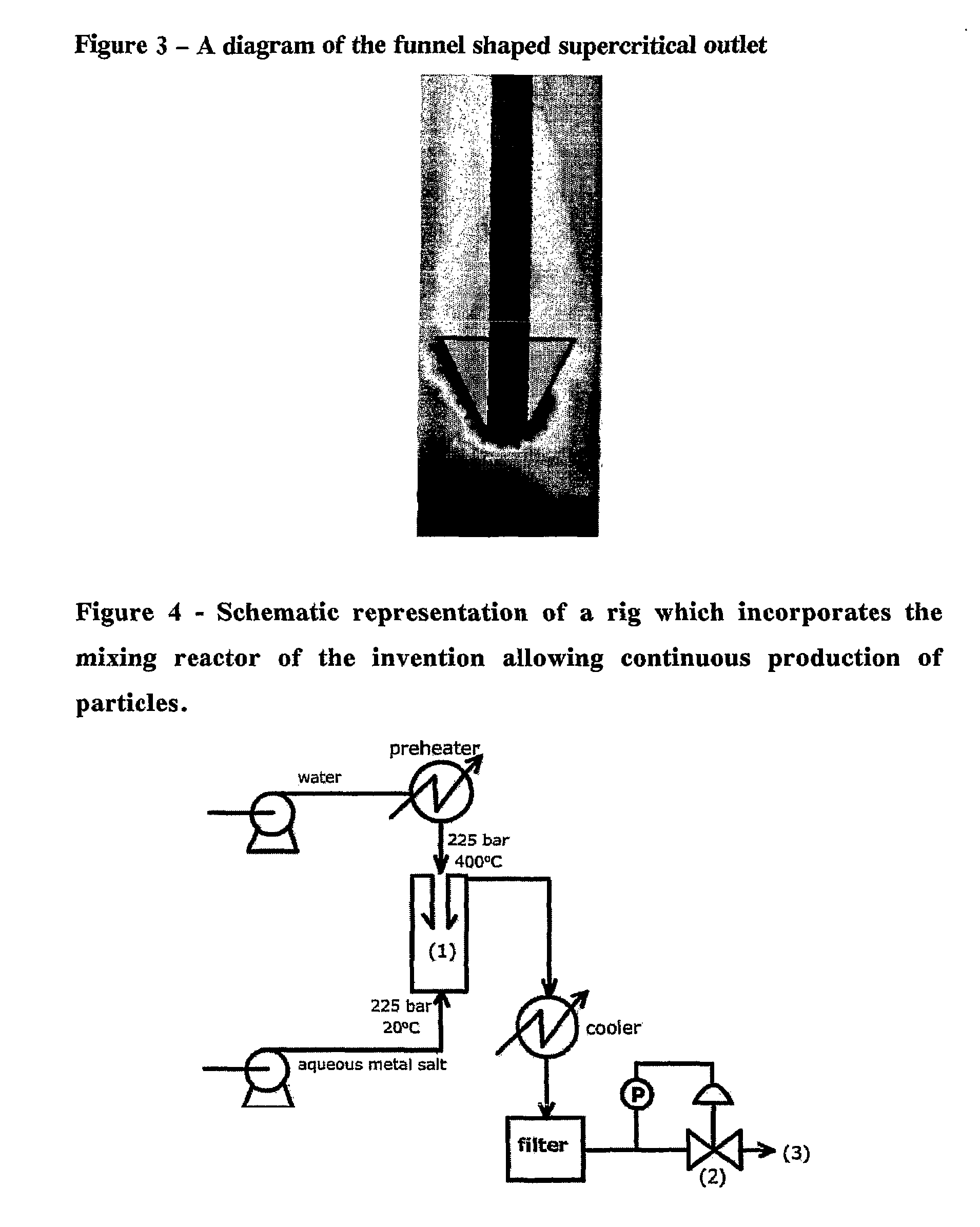
[0043]The following reaction was carried out using the mixing reactor of the invention incorporated into a rig configuration shown in FIG. 4.

Hydrolysis: Ce(NO3)4+4H2O→Ce(OH)4(s)+4HNO3

Dehydration: Ce(OH)4→CeO2+2H2O

[0044]System pressure was set to 228 bar. The metal salt solution (Ce(NO3)4, (0.2 M)) was flowed at 5 ml / min through the reactor. A total of 250 ml of the metal salt solution was used during the course of the 50 min run. The scH2O was flowed at 10 ml / min through the reactor at a temperature of 400° C. The reactor was maintained at a temperature of 370° C. using a band heater for the duration of the reaction.

[0045]The high pressure pumps and back pressure regulator system allow the pressure to be maintained throughout the rig and then to be reduced at the end allowing liquid product to be released at ambient temperature and pressure. The rig, using the invention can be run for hours without blocking producing 2-5 g per h...

example 2

Control Over Surface Area with Flow Rate within the Reactor

[0048]FIG. 5 shows the effect of increasing flow rate of cerium nitrate up through the reactor. Clearly there is an interesting trend of increasing surface area (from 65 m2 / g up to 100 m2 / g) with increasing metal salt flow up to a value of 8 ml / min beyond which the particle size begins to decrease. It is possible that the increase is caused by the relationship between flow velocity and reaction kinetics and the decrease is caused by an ‘excess’ of metal salt resulting in larger particles being produced.

example 3

Control Over Surface Area with Temperature within the Reactor

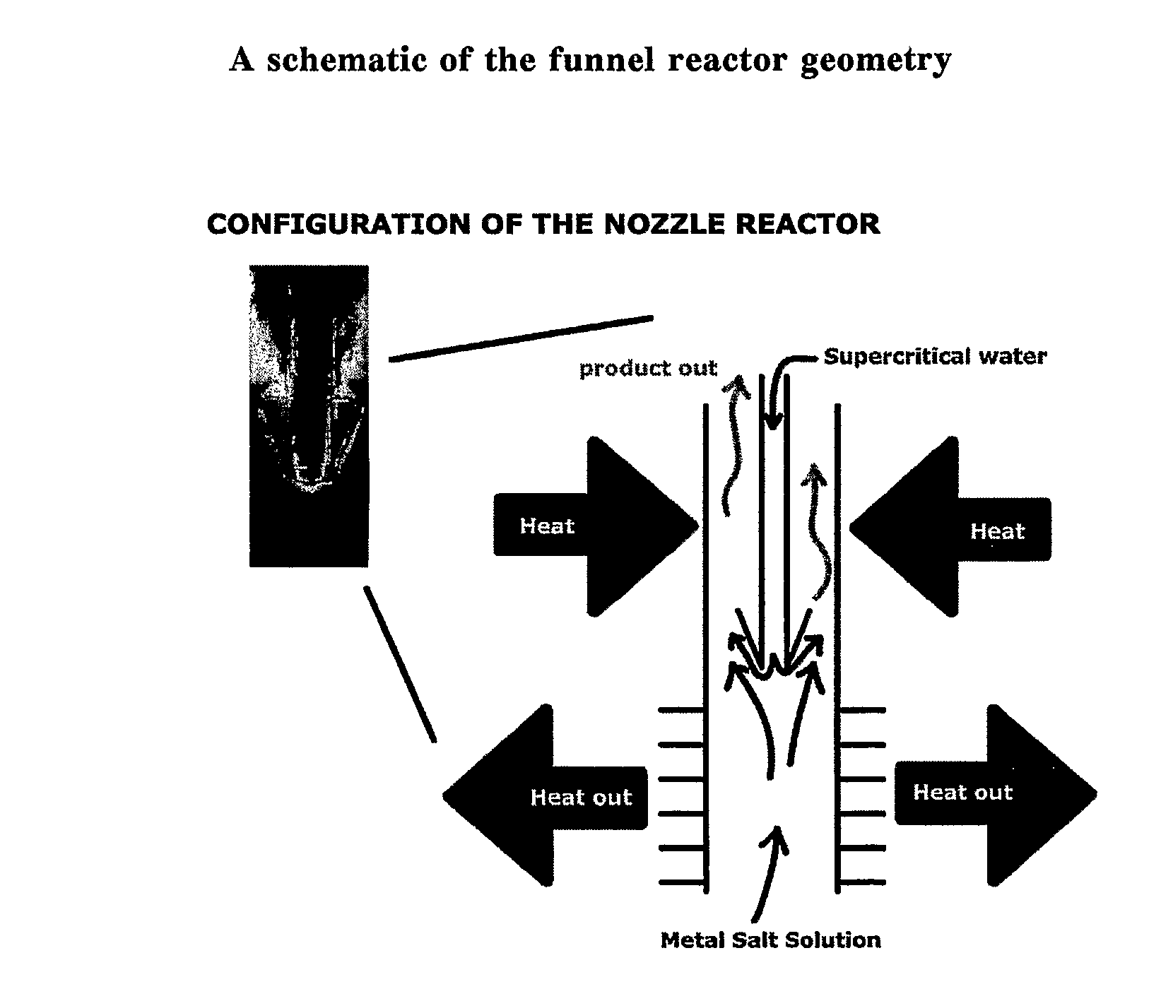
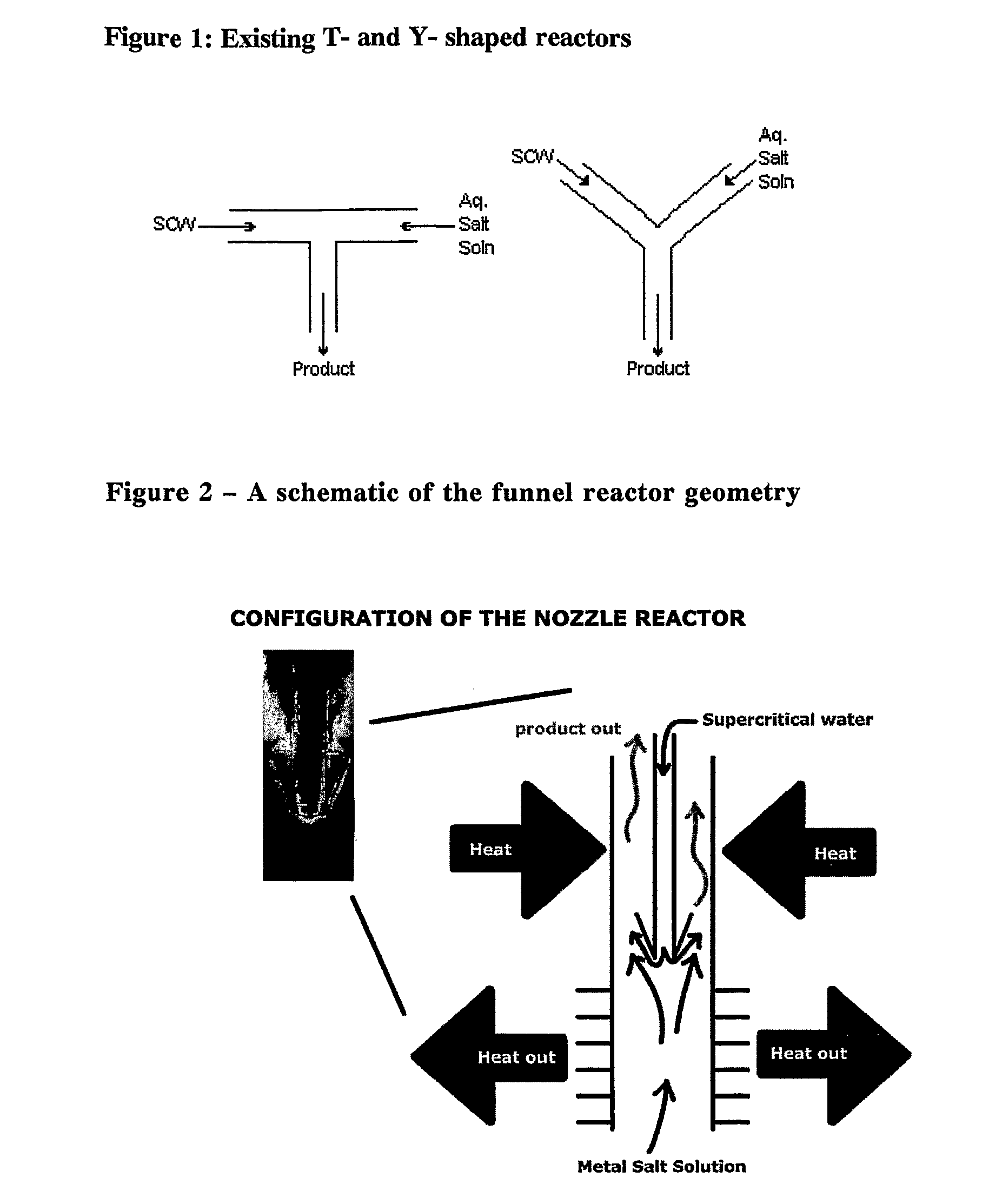
[0049]One area of interest is the effect of the operating temperature within the reactor and it's impact on surface area. The reactor can be heated externally to any given temperature sub, near or super critical, the relationship between surface area (and indirectly, particle size) and operating temperature can be established. Even though the heated water inlet inside the reactor may be operating sub critical, the temperature differential between the metal salt and the heated water still exists and this will cause the inlet flow to turn upwards into the downstream outlet of the pipe, as shown in FIG. 2.

[0050]FIG. 6 is a graph showing how surface area increases significantly with operating temperature. This indicates that the particle size (and possibly the morphology) can be tailored by adjusting the operating conditions of the reactor.


PUM

PropertyMeasurementUnit
temperatureaaaaaaaaaa

Abstract

A mixing reactor for mixing efficiently streams of fluids of differing densities. In a preferred embodiment, one of the fluids is supercritical water, and the other is an aqueous salt solution. Thus, the reactor enables the production of metal oxide nanoparticles as a continuous process, without any risk of the reactor blocking due to the inefficient mixing inherent in existing reactor designs.

Description

[0001]This application is the U.S. national phase of PCT Application No. PCT / GB05 / 00483 filed on Feb. 11, 2005, which claims priority under 35 USC 119 to British Patent Application No. 0402963.3 filed on Feb. 11, 2004, the contents of which are herein incorporated by reference in their entirety.FIELD OF THE INVENTION[0002]The invention is a counter current mixing reactor enabling the efficient mixing of streams of fluid. More specifically, one stream may be of a heated, pressurised or supercritical fluid whilst another is of a denser fluid. More preferably, one stream may be of supercritical water (scH2O), and another is of a metal containing solution. Most preferably, the invention can be used in the continuous synthesis of nanoparticles of metals or metal oxides in high temperature water without blockage of pipeworks and with improved control of particle size and shape compared to previous designs of reactor.BACKGROUND OF THE INVENTION[0003]Metal and metal oxide particles with nan...

Claims


Application Information

Patent Timeline
Patent Type & Authority Patents(United States)
IPC IPC(8): C01F17/00B82B1/00C01G49/02C01G55/00C01G57/00C01G5/00C01G3/02C01G11/00C01G23/047C01G25/02B82B3/00B01F3/04B01F3/08B01F5/00B01F5/04B01J3/00B01J19/24B22F1/054B22F9/24C01B13/36C01F17/235C01G1/02C01G9/02C01G23/04C01G99/00
CPCB01F3/0873B01J3/008B01J19/2415B22F1/0018B22F9/24B82Y30/00C01B13/36C01B13/363C01F17/0043C01G1/02C01G3/02C01G5/00C01G9/02C01G11/00C01G23/04C01G25/02C01G49/02C01G55/004B01F5/045Y10S977/94B01F2003/0064B01F2005/0034B01J2219/00094B22F2999/00C01P2004/64C01P2006/12Y10S977/813Y10S977/70Y10S977/895Y10S977/773Y10S977/811Y10S977/90Y10S977/81B22F2202/03Y02P20/54C01F17/235B22F1/054B01F23/043B01F23/453B01F2025/918B01F25/313B01J3/00B01J19/24B82Y40/00B01F23/40
Inventor LESTER, EDWARD HENRYAZZOPARDI, BARRY JAMES
Owner PROMETHEAN PARTICLES
Why Eureka
Try Eureka