Encoder, lens-implement and digital camera

a technology applied in the field of encoder and lens, can solve the problem that the magnetic scale cannot be correctly read by the magnetic sensor

Inactive Publication Date: 2009-07-28
OLYMPUS CORP
View PDF25 Cites 26 Cited by
  • Summary
  • Abstract
  • Description
  • Claims
  • Application Information

AI Technical Summary

Benefits of technology

[0016]The encoder according to the present invention includes: a magnetic sensor attached to a stationary member; a magnetic scale arranged with one portion fixed to a movable member such that relative travel can be attained with respect to the magnetic sensor with the scale face directed toward the magnetic sensor; and a pressure unit attached to the stationary member for pressing the portion not fixed to the movable member of the magnetic scale against the magnetic sensor from the opposite side of the scale surface so that the scale surface of the magnetic scale can slide against the detection unit of the magnetic sensor.

Problems solved by technology

In the meantime, the position detection device using the magnetic resistance element has the problem that a magnetic sensor cannot correctly read the magnetic scale unless the magnetic resistance element (magnetic sensor) and the magnetic scale can be maintained at a predetermined interval.

Method used


Image

  • Encoder, lens-implement and digital camera
  • Encoder, lens-implement and digital camera
  • Encoder, lens-implement and digital camera

Examples


Embodiment Construction

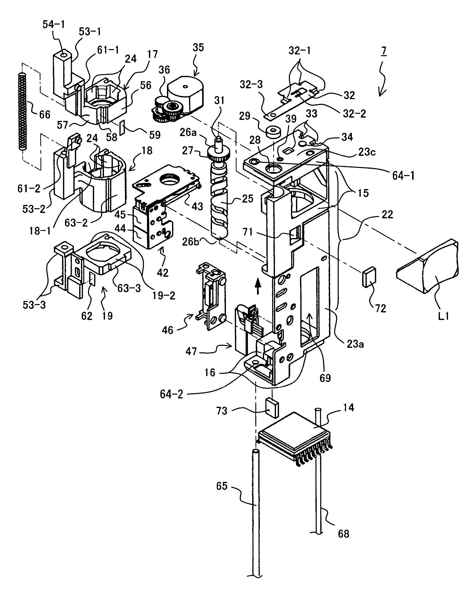
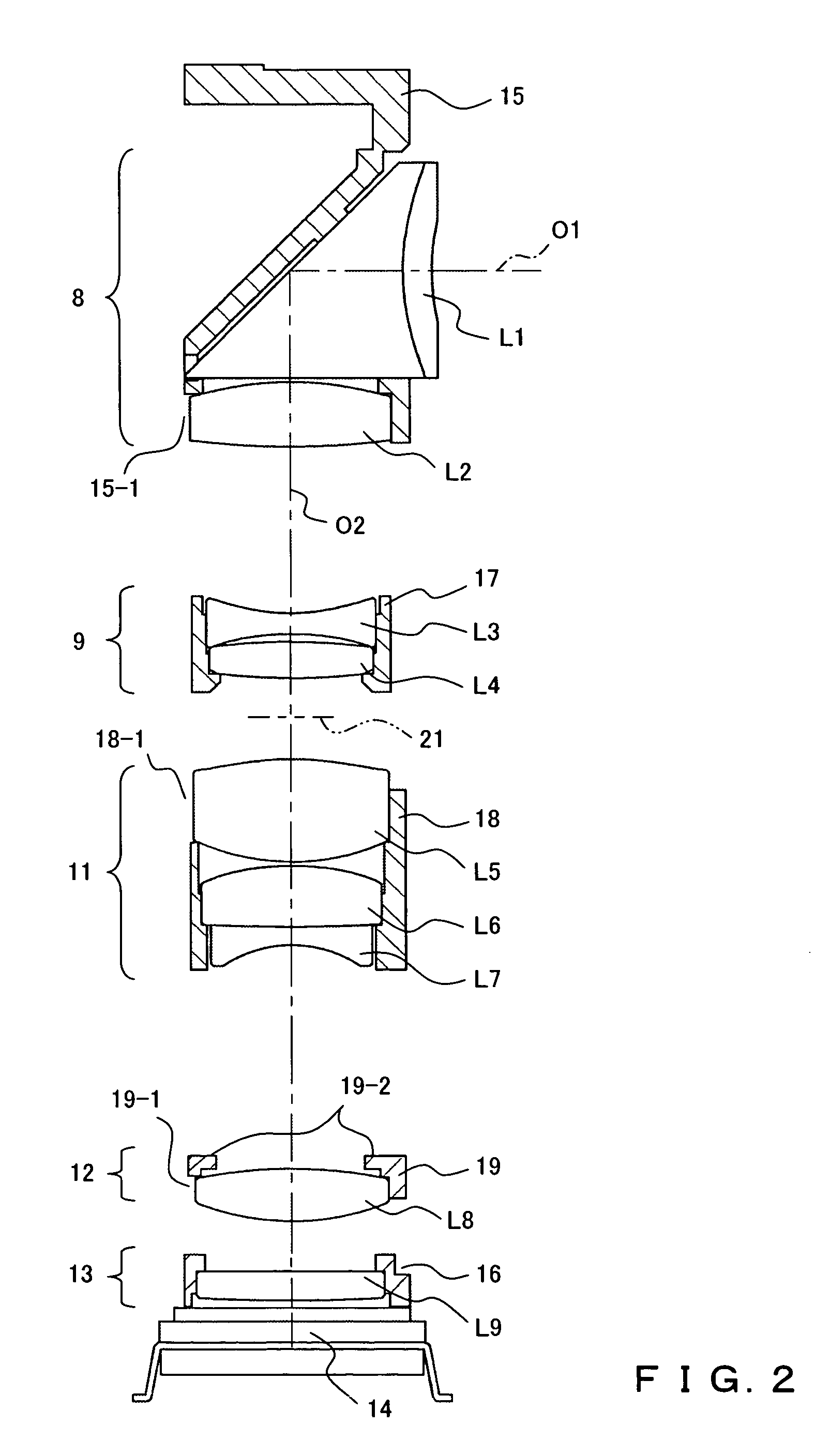
[0040]The embodiments of the present invention are explained below by referring to the attached drawings. In the following explanation, the above-mentioned one main surface is formed by, for example, the surface of a metal frame 23a and the surface of a first fixed lens frame unit 15, etc. incorporated into the metal frame 23a. The other opposing main surface is an open surface. The optical element is formed by, for example, a prism L1, lenses L2 through L9, etc. The reflective optical element is formed by the prism L1, etc. The mold unit is formed by, for example, the first fixed lens frame unit 15, a second fixed lens frame unit 16, etc. One side is formed by, for example, a metal frame 23b, and the other side is an open surface. A first guide member is formed by, for example, a first guide shaft 65, etc., and a second guide member is formed by a second guide shaft 68, etc. A first guide member support unit is formed by, for example, guide shaft support holes 64 (64-1, 64-2), etc....


PUM


Abstract

All members of a lens-implement are arranged in a rectangular space of a main lens frame. A lens prism is fixed, three movable lens frames for zoom and focusing inserted the two guide shafts are arranged, and a image capturing lens is fixed top-to-bottom seriatim occupying the horizontal ⅔ portion of the rectangular space, and the image capturing device is arranged at foot portion. A zoom motor is arranged at the back of the lens prism, and a zoom shaft cam, a diaphragm / shutter, a focusing ultrasonic linear motor, and a magnetic sensor are arranged along the lens frames.

Description

CROSS REFERENCE TO RELATED APPLICATION[0001]This application is based upon and claims the benefit of priority from the prior Japanese Application No. 2003-172159, No. 2003-172142, No. 2003-172154, No. 2003-172169, filed Jun. 17, 2003, the entire contents of which are incorporated herein by reference.BACKGROUND OF THE INVENTION[0002]1. Field of the Invention[0003]The present invention relates to a simple architectonics high-precision encoder, a slim lens-implement using the encoder, and a digital camera using the lens-implement.[0004]2. Description of the Related Art[0005]Conventionally, with a growing demand for a smaller and slimmer digital camera in the digital camera market, a slim lens-implement incorporated into a digital camera has been required.[0006]As one of the methods of providing a slimmer lens-implement, a lens-implement based on a bent-optical-axis optical system has been proposed. For a slimmer device, the Applicant has proposed a lens-implement configured by arrangin...

Claims


Application Information

Patent Timeline
Patent Type & Authority Patents(United States)
IPC IPC(8): G02B13/16G02B23/24H04N5/225H04N5/238G02B7/28
CPCG02B7/28
Inventor IKEMACHI, MASARUSHIRATORI, KAZUTOSHISATO, TOMOAKI
Owner OLYMPUS CORP
Why Eureka
Try Eureka