Elevator car with car electrical system integrated in the car roof and method of mounting an elevator installation

a technology of car electrical system and elevator, which is applied in the direction of elevators, transportation and packaging, building lifts, etc., can solve the problems of increasing the height of construction, increasing the risk of accidents, and the inability to control the elevator in service operation, so as to reduce the risk of accidents, and increase the standing area

Active Publication Date: 2009-08-04
INVENTIO AG
View PDF7 Cites 11 Cited by
  • Summary
  • Abstract
  • Description
  • Claims
  • Application Information

AI Technical Summary

Benefits of technology

[0010]An object of the present invention is to arrange the car electrical system, which is required for operation of the car, in such a manner that control of the car for service operation is possible, that sufficiently large standing areas are present, that it does not cause any additional constructional height, that it can be mounted with low cost and that the risk of accident is reduced as far as possible. In addition, the car electrical system shall be arranged economically and, for the purpose of maintenance, it shall be accessible in simple, safe and rapid manner.
[0012]According to the present invention the apparatus space which is used for arrangement of parts of the car electrical system is now arranged along an outer boundary of the car roof or along a car roof edge. The car roof space has in the region of the car roof edge the fastening points required for fastening parts of the car electrical system. The car roof space given by the construction of the roof is thereby utilized in an optimum manner and no additional constructional space is required. The mounting cost for the car electrical system is substantially reduced, since the car roof can be wired and equipped with the car electrical system at the factory in the most suitable environment. The corresponding cost in the field is eliminated and the cost-efficiency of the product is improved particularly also because the car electrical system can be largely checked with respect to function in the factory.
[0013]The apparatus space or the region of the car roof containing the car electrical system is preferably arranged along a lateral boundary of the car roof, wherein this lateral boundary usually extends at right angles to the boundary which is associated with the main car entrance. The lateral arrangement means that the apparatus space, considered from a floor access, is arranged at the left-hand or right-hand boundary edge of the car roof. The car roof can thereby be easily walked on, for the purpose of maintenance, with use of a floor entrance, since no large parts of the car electrical system are arranged in the region of the main entrance opening and the car roof can thereby be freely walked on. The region of the car roof which is constructed for accommodation of the car electrical system is advantageously confined to a region which is less than ⅓ of the corresponding car dimension or comprises less than ⅓ of the car roof area. If the car electrical system is arranged at a lateral boundary of the car roof, the apparatus space used for accommodation of the car electrical system advantageously occupies less than ⅓ of the car width. Due to this arrangement, the rest of the car roof area has a sufficient standing area in order to be able to offer a sufficiently large, unified work area for the service specialist.

Problems solved by technology

The disadvantage of this solution is:The box is placed on the car roof and causes additional constructional height.In order to be able to walk on the car roof the box has to be stepped over or steps are formed which hamper the operations and, in particular, walking on the car roof.The mounting effort is substantial, since the box is mounted and wired only on assembly of the car at the construction site.The cover of the box is removed for the purpose of maintenance.
This increases the risk of accident when the maintenance person, with the electrical covering removed, stands on the car or when the cover is not mounted in the case of car journeys which follow.
The disadvantages of this solution are that control of the elevator in service operation is not available and that in the case of an open maintenance hatch the car roof area which can be walked on is small.

Method used


Image

  • Elevator car with car electrical system integrated in the car roof and method of mounting an elevator installation
  • Elevator car with car electrical system integrated in the car roof and method of mounting an elevator installation
  • Elevator car with car electrical system integrated in the car roof and method of mounting an elevator installation

Examples


Embodiment Construction

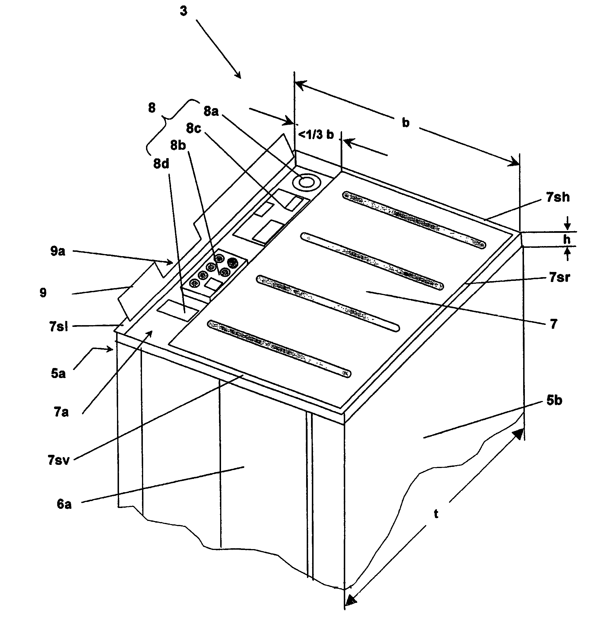
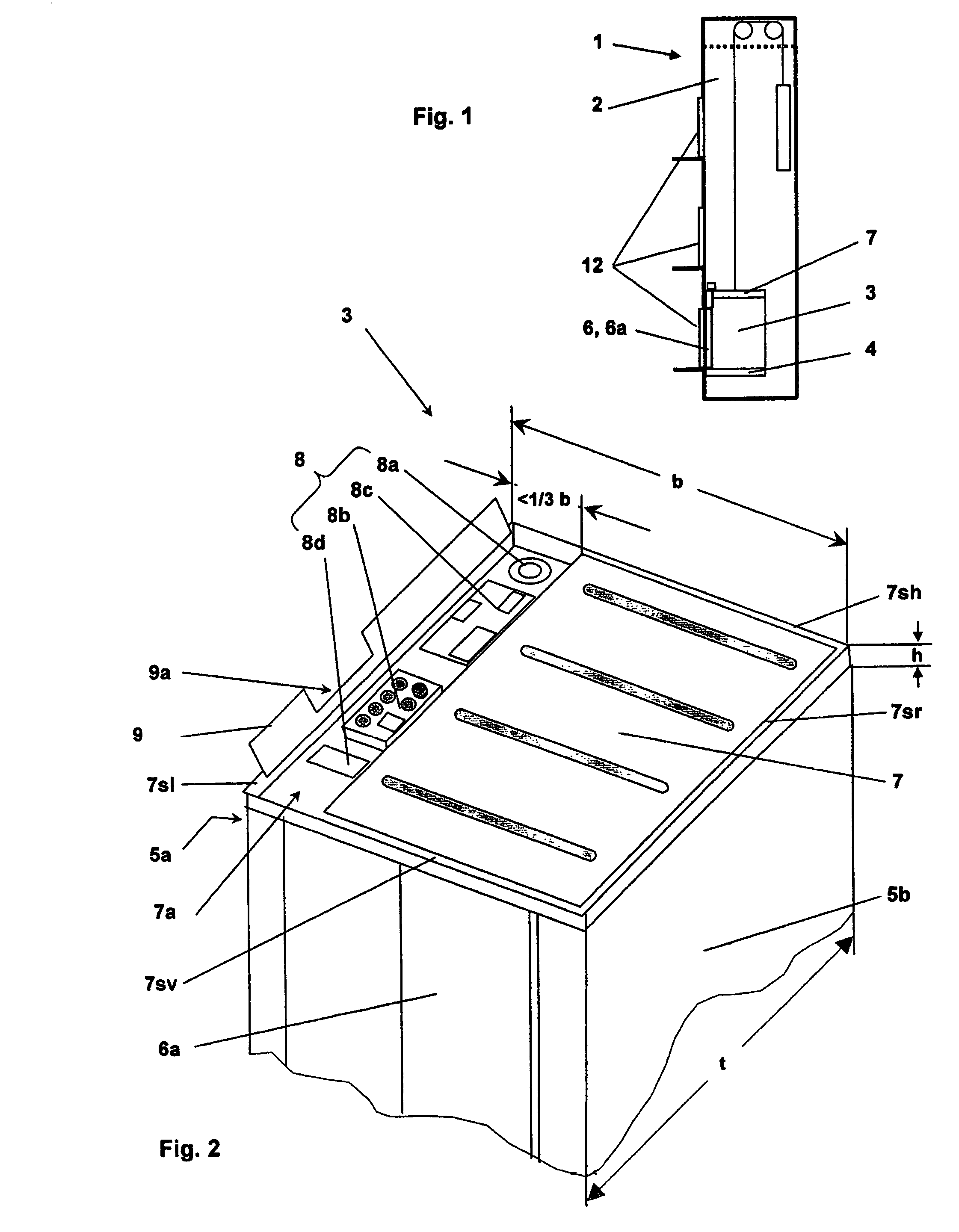
[0018]An elevator installation 1 consists, as illustrated in FIG. 1 by way of example, of an elevator car 3 which is arranged in an elevator shaft 2 to be movable along a substantially vertical axis. The elevator car 3 serves primarily for the movement of persons and / or goods. The elevator car 3 consists of a car floor 4, side walls 5a, 5b, a front wall containing a car entrance 6, a back wall and a car roof 7. The access to the elevator car 3 is made possible via at least one of the car entrance 6 and via floor entrances 12. If the elevator car 3 has more than one car entrance 6, a main car entrance 6a is defined. The elevator car 3 is, in the illustrated example, connected with a counterweight by means of support means and moved by means of a drive. The arrangement of the drive is not critical for this invention and the elevator car can, in addition, be executed in the form of a self-propelled vehicle.

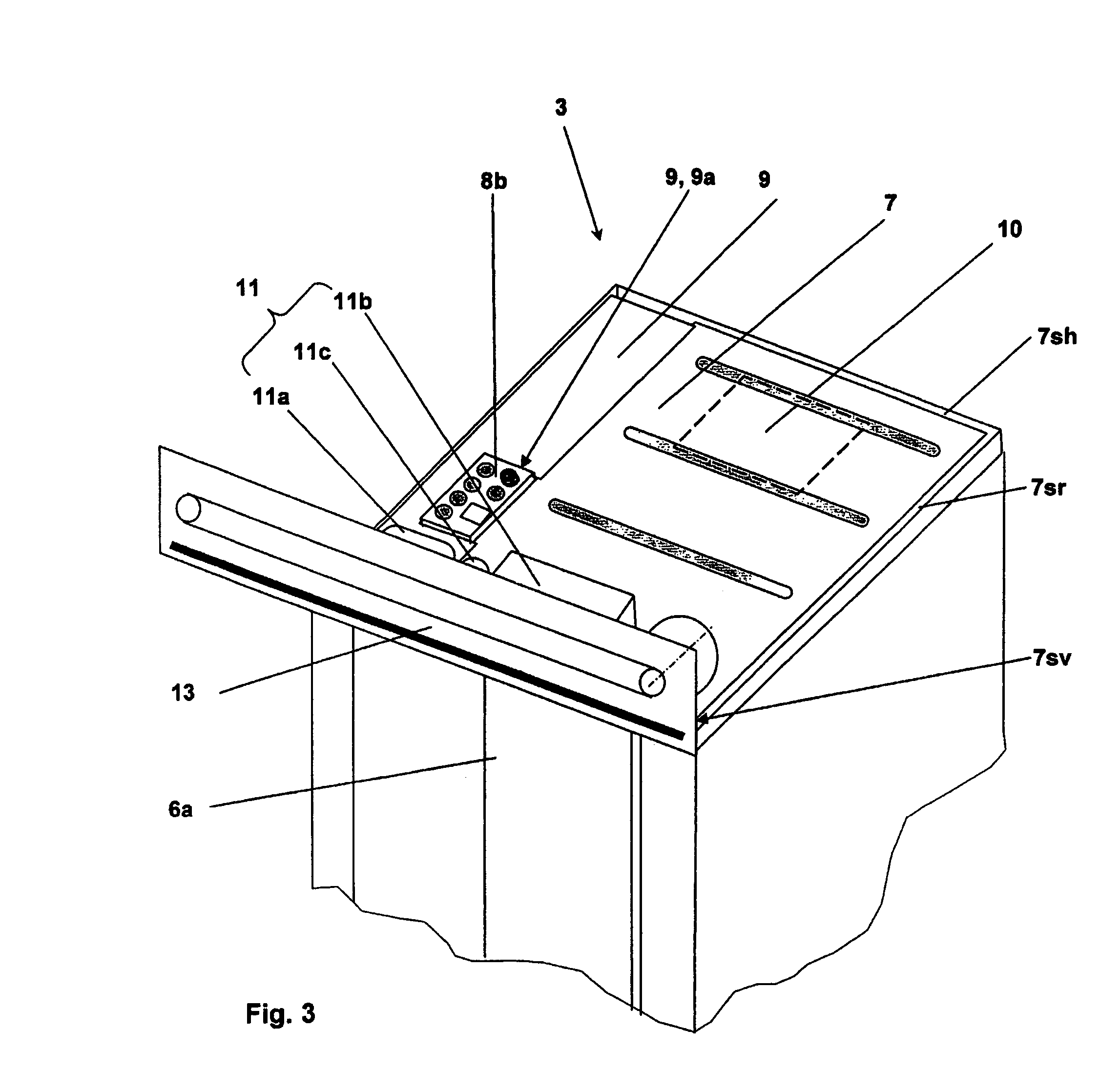
[0019]The car roof 7 closes the elevator car 3, as shown in FIGS. 2 and 3, at th...


PUM


Abstract

A portion of an elevator car electrical system, such as car computer, terminals, communication apparatus, etc., is mounted in an apparatus space integrated into a car roof. The apparatus space is arranged along a car roof edge and utilizes a constructional height required for stiffening the car roof. The portion of the car electrical system is accessible by a moveable cover for service. When closed, the cover forms a standing surface which can be used for servicing in the elevator shaft.

Description

BACKGROUND OF THE INVENTION[0001]The present invention relates to an elevator installation with a car electrical system integrated in the car roof and a method for mounting an elevator installation.[0002]The elevator installation comprises an elevator car movable in an elevator shaft. The elevator car essentially consists of a car floor, side walls, at least one car entrance and a car roof. Access to the car takes place in normal operation of the elevator installation by way of a floor entrance and the car entrance.[0003]Different electrical or electromechanical apparatus and installations necessary for operation of the elevator installation are, as a rule, arranged in the region of the car roof. These apparatus and installations are, for example, the door control, evaluating apparatus for shaft information and / or for door monitoring, apparatus for operation of the installation in service operation, communications apparatus, energy storage apparatus, parts of the car lighting and / or...

Claims


Application Information

Patent Timeline
Patent Type & Authority Patents(United States)
IPC IPC(8): B66B11/02B66B5/00B66B7/00
CPCB66B11/0233B66B11/0226B66B11/02B66B1/46B66B1/50
Inventor ROSSIGNOL, ERIC
Owner INVENTIO AG
Why Eureka
Try Eureka