Sunshade assembly

a technology of sunshade and assembly, which is applied in the direction of roofs, mechanical equipment, transportation and packaging, etc., can solve the problems of large interior cabin space occupied by conventional sunshade assembly and user's inability to arbitrarily set the sunshade screen to any desired position

Inactive Publication Date: 2009-08-04
MACAUTO IND CO LTD
View PDF17 Cites 42 Cited by
  • Summary
  • Abstract
  • Description
  • Claims
  • Application Information

AI Technical Summary

Benefits of technology

[0006]According to the present invention, a sunshade assembly that is adapted to be used on a sunroof of a vehicle includes a pair of spaced-apart rails, a roller unit, a screen, and a position-retaining unit. Each of the rails has opposite front and rear ends, and is formed with a track therealong. The roller unit is spaced apart from the front end of each of the rails, and includes an inner tube member, and an outer tube member rotatably sleeved on the inner tube member. The screen has a fixed end secured to the outer tube member, a free end opposite to the fixed end, and opposite peripheral edge portions each extending into the track of a respective one of the rails. The position-retaining unit includes an annular spool defining a center space and disposed on one end of the outer tube member, a rope, and a spiral spring. The rope extends along one of the rails, is looped around the rear end of said one of the rails, and is passed through the track in said one of the rails. The rope has a first end secured to the spool, and a second end secured to the free end of the screen. The spiral spring is disposed in the center space of the spool, and has an inner end connected to the one end of the outer tube member and an outer end connected to the spool.

Problems solved by technology

Hence, a user cannot arbitrarily set the sunshade screen to any desired position.
However, the vast majority of winding rollers for sunshade assemblies is formed as a horizontal straight bar that does not conform to the arched shape of the underside roof panel of the vehicle.
As a result, the conventional sunshade assembly occupies a significant amount of interior cabin space.

Method used


Image

  • Sunshade assembly
  • Sunshade assembly
  • Sunshade assembly

Examples


Embodiment Construction

[0014]The preferred embodiment of a sunshade assembly according to the present invention may be mounted on a vehicle (not shown) so as to cover a sunroof of the vehicle.

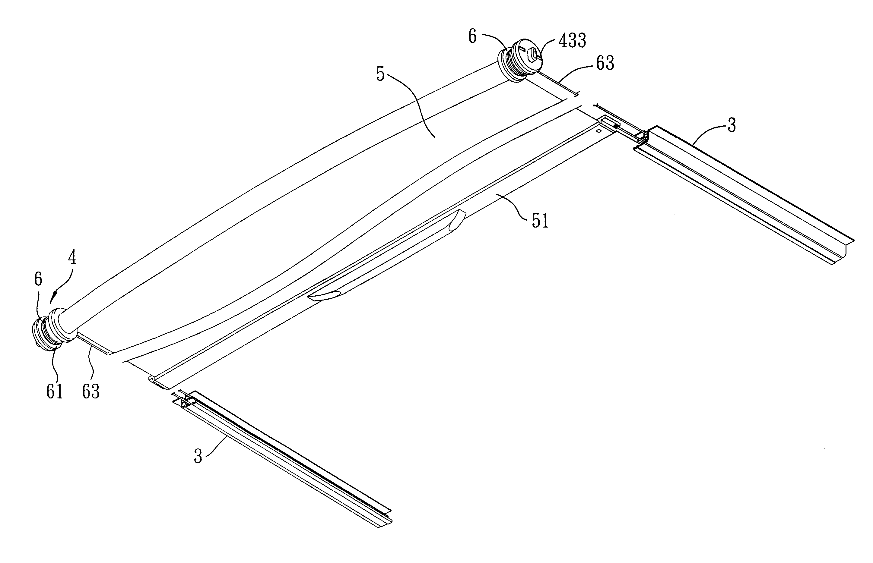
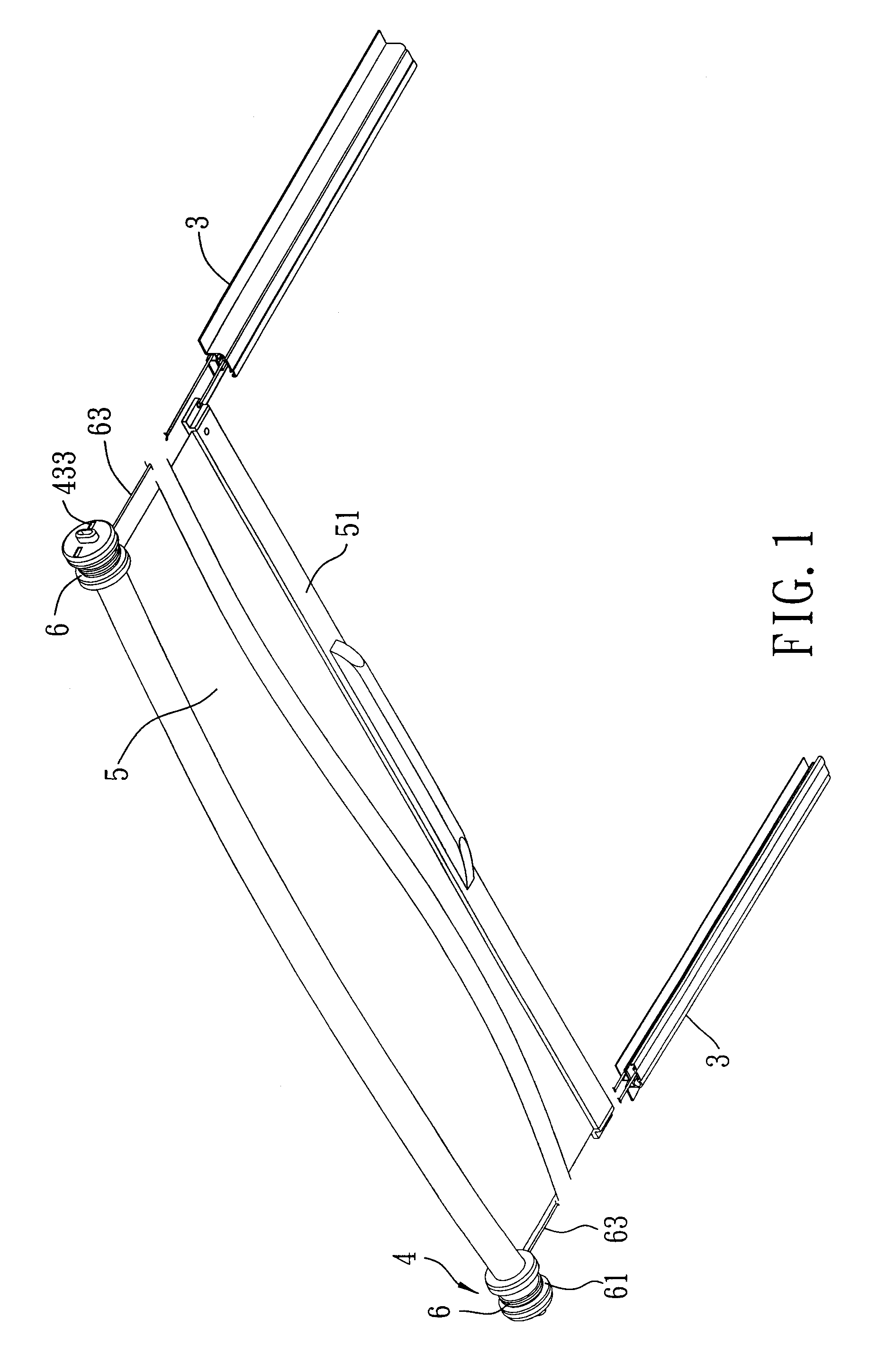
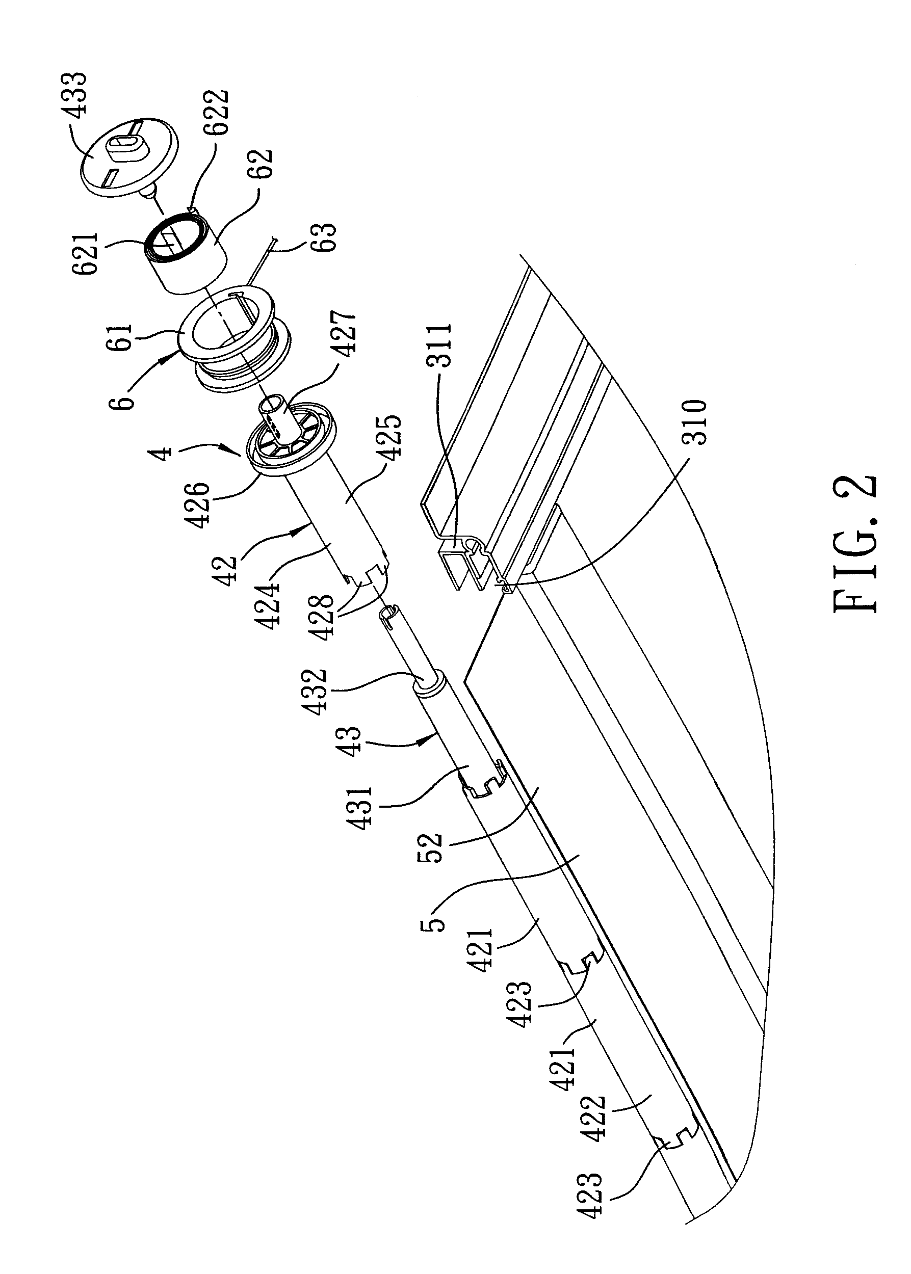
[0015]Reference is made to FIGS. 1 to 4. The sunshade assembly includes a pair of spaced-apart rails 3, a roller unit 4, a screen 5, and a position-retaining unit 6. Each of the rails 3 has opposite front and rear ends, and is formed with a track 310 and a recess 311 therealong. The track 310 has an opening that faces the track 310 of the other rail 3. The recess 311 is parallel to and above the track 310. Each rail 3 includes a pulley 32 rotatably disposed at the rear end thereof.

[0016]The roller unit 4 is spaced apart from the front end of the rails 3, and includes an inner tube member 43 that is fixedly assembled onto the vehicle, and an outer tube member 42 sleeved on the inner tube member 43 and rotatably driven relative to the inner tube member 43.

[0017]The screen 5 has a fixed end 52 secured to the outer tube ...


PUM


Abstract

A sunshade assembly includes a pair of spaced-apart rails, a roller unit, a screen, and a position-retaining unit. Each rail has opposite front and rear ends, and is formed with a track therealong. The roller unit is spaced apart from the front end, and includes an inner tube member and an outer tube member. The screen has a fixed end secured to the outer tube member, a free end, and opposite peripheral edge portions extending into the tracks. The position-retaining unit includes an annular spool, a rope, and a spiral spring. The rope extends along one of the rails, loops around the rear end, and passes through the track in the rail. The spiral spring is disposed in the spool, and has an inner end connected to the outer tube member and an outer end connected to the spool.

Description

BACKGROUND OF THE INVENTION[0001]1. Field of the Invention[0002]The invention relates to a sunshade assembly, more particularly to a sunshade assembly for a vehicle, in which the sunshade assembly has a screen that may be extended to and maintained at any desired position.[0003]2. Description of the Related Art[0004]To prevent sunlight from entering through a sunroof, car owners and car manufacturers sometimes mount a sunshade assembly on the sunroof. In order to meet the diverse demands of these car owners and car manufacturers, sunshade manufacturers have designed many different types of sunshade assemblies. These sunshade assemblies are different primarily with respect to the design of their retraction mechanism. European Patent EP1598517, entitled “ROLLER BLIND WITH SPRING MOTOR,” discloses a retraction mechanism that utilizes a spiral spring to retract a sunshade screen automatically. However, this sunshade assembly requires the installation of a plurality of positioning struct...

Claims


Application Information

Patent Timeline
Patent Type & Authority Patents(United States)
IPC IPC(8): B60J3/02
CPCB60J7/0015B60J1/2058B60J1/2025
Inventor LIN, PAUL
Owner MACAUTO IND CO LTD
Why Eureka
Try Eureka