Rigid support structure on two legs for CPR

a support structure and patient technology, applied in the field of rigid support structures for fixing patients to treatment units, can solve the problems of patient not being secured, treatment accuracy decreasing, and not being able to compress the desired body part, so as to achieve simple, accurate and effective cardiopulmonary resuscitation, the effect of improving the accuracy

Inactive Publication Date: 2009-08-04
PHYSIO CONTROL INC
View PDF31 Cites 112 Cited by
  • Summary
  • Abstract
  • Description
  • Claims
  • Application Information

AI Technical Summary

Benefits of technology

[0008]An object of the present invention is to improve the accuracy when providing external treatment to a patient by means of a treatment unit. An aspect of the object is to provide fixation of the patient in relation to a treatment unit. Another aspect of the object is to enable treatment to a patient when the patient is transported on for example a stretcher. Yet another aspect of the object is to enable simple, accurate and effective cardiopulmonary resuscitation of a person suffering from a cardiac arrest.

Problems solved by technology

A drawback with the disclosed apparatus is that the patient is not secured to the apparatus and it is for example possible for the patient to move in relation to a compressor pad (19) whereby the treatment accuracy decreases.
A drawback with this apparatus is that the front part (Y) may be obliquely fixated to the back plate (X), since the height of each leg of the front part (Y) is adjusted one by one using one of the knobs.
Yet another drawback is that the patient is not fixated to the apparatus whereby it is possible for the patient to move in relation to the compression means, which in the worst scenario causes a not desired body part to be compressed.
A drawback with the disclosed apparatus is that it is not easy to handle and position to provide a quick start of the cardiac massage.

Method used


Image

  • Rigid support structure on two legs for CPR
  • Rigid support structure on two legs for CPR
  • Rigid support structure on two legs for CPR

Examples


Embodiment Construction

[0037]The present invention will now be described in more detail with reference to the accompanying figures.

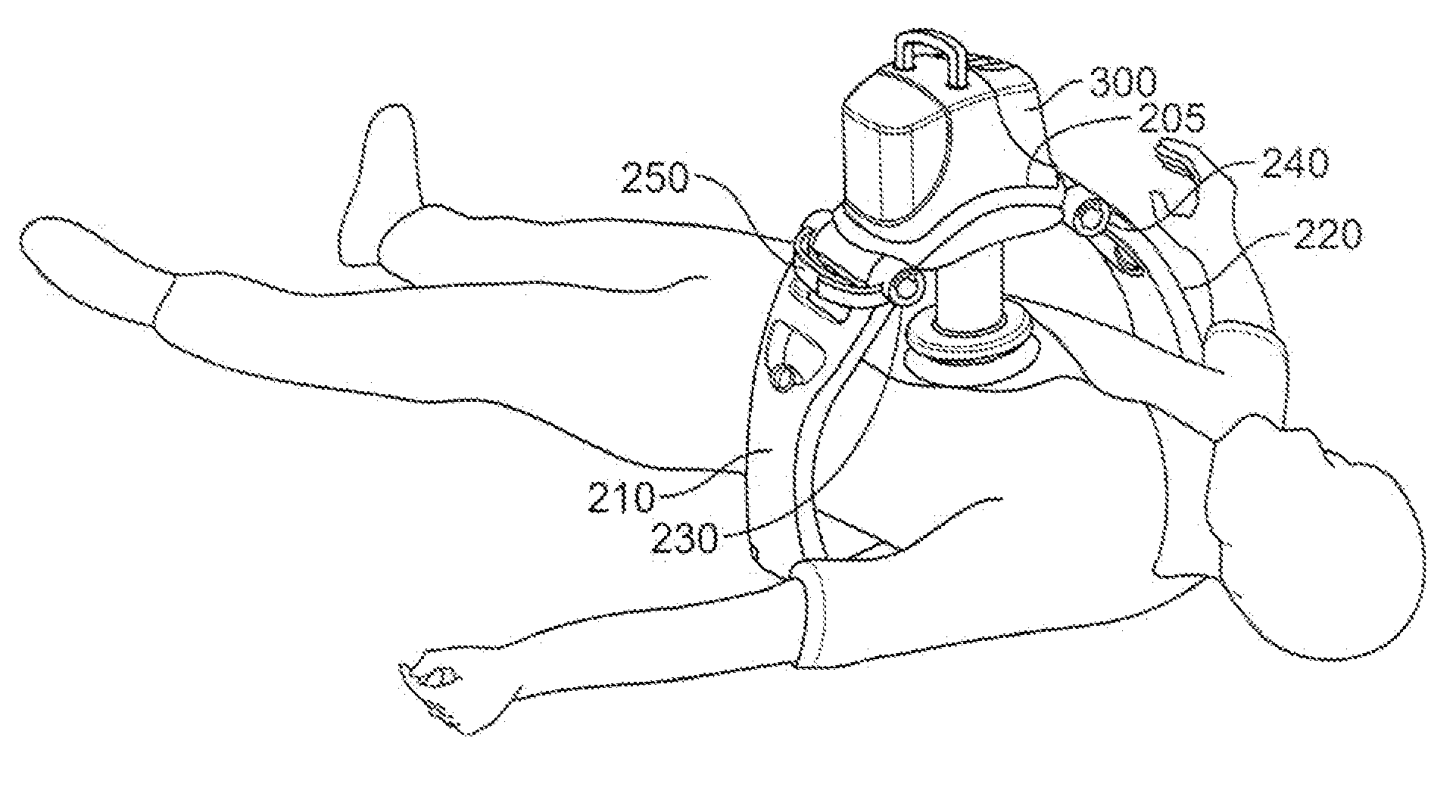
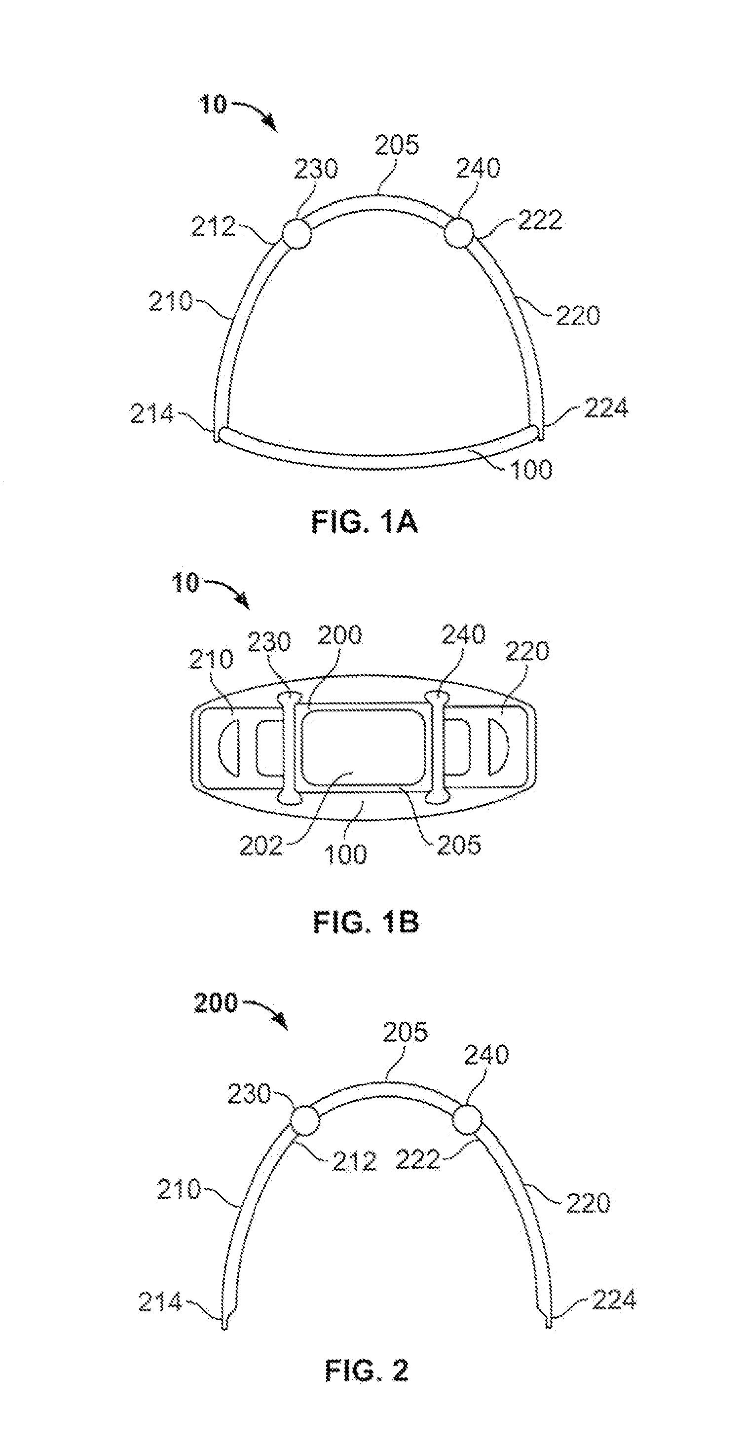
[0038]FIGS. 1a and 1b show a front view and a top view, respectively, of an embodiment of a support structure 10 according to the invention. The support structure 10 comprises a base or back plate 100 arranged to be positioned posterior of the patient, e.g. behind the back of a patient to be treated. More specifically, the back plate 100 is arranged to be positioned posterior to the body part to be treated. The support structure 10 comprises further a front part or upper part 200 arranged to be positioned around the patient anterior of the body part to be treated. Further, the front part 200 of the support structure 10 comprises a central part 205 and two legs 210, 220, which legs are arranged to be removably attached or secured at the base plate 100 by means of snap locking or spring latch.

[0039]An embodiment of a back plate 100 is schematically shown in FIG. 4. The back plat...


PUM


Abstract

The present invention relates generally to a support structure for fixating a patient to a treatment unit, and especially to a support structure for fixating the patient to a cardiopulmonary resuscitation unit. An embodiment of the support structure (10) comprises a back plate (100) for positioning behind said patient's back posterior to said patient's heart and a front part (200) for positioning around said patient's chest anterior to said patient's heart. Further, the front part (200) can comprise two legs (210, 220), each leg (210, 220) having a first end (212, 222) pivotably connected to at least one hinge (230, 240) and a second end (214, 224) removably attachable to said back plate (100). Said front part (200) can further be devised for comprising a compression / decompression unit (300) arranged to automatically compress or decompress said patient's chest when said front part (200) is attached to said back plate (100).

Description

FIELD OF INVENTION[0001]The present invention relates generally to a support structure for fixating a patient to a treatment unit, and especially to a support structure for fixating the patient to a cardiopulmonary resuscitation unit.BACKGROUND OF INVENTION[0002]When a person suffers from a cardiac arrest, the blood is not circulating to nourish the body, which can lead to death of or cause severe bodily damages to the person. To improve the person's chances to survive or to minimize the damages at cardiac arrest it is essential to take necessary measures as quickly as possible to maintain the person's blood circulation and respiration, otherwise the person will succumb to sudden cardiac death in minutes. Such an emergency measure is cardiopulmonary resuscitation (CPR), which is a combination of “mouth-to-mouth” or artificial respiration and manual or automatic cardiac compression that helps the person to breathe and maintains some circulation of the blood.[0003]However, CPR does no...

Claims


Application Information

Patent Timeline
Patent Type & Authority Patents(United States)
IPC IPC(8): A61H31/00
CPCA61H31/00A61H31/008A61H31/004A61H31/007A61H2201/1253A61H2205/084
Inventor SEBELIUS, PETERBERGSTROM, PERHAMPF, JAN
Owner PHYSIO CONTROL INC
Why Eureka
Try Eureka