Body orthosis

Active Publication Date: 2009-08-04
SHIYOMI PROSTHETIC MFG
View PDF20 Cites 11 Cited by
  • Summary
  • Abstract
  • Description
  • Claims
  • Application Information

AI Technical Summary

Benefits of technology

[0008]Thus, by setting a rotational load to the plantar flexion side larger than that to the dorsiflexion side, when the landed foot is lifted, the foot can be held by the body orthosis at an angle of the foot immediately before the lifting. Moreover, a load applied by a part of weight caused by the landing of the foot is converted into a rotating force for rotating the body protective member. Accordingly, even when a large rotational load is set, the body protective member can be smoothly rotated.
[0020]The body orthosis of the present invention may be installed beforehand in the shoe. Since the loading portion or the like are housed beforehand in the shoe, the body orthosis can be worn without discomfort and can even be used for exercise or the like.

Problems solved by technology

This is because inward bending of a foot directs its sole inward, and impossibility of controlling an ankle causes a tiptoe side of the foot (referred to toe, hereinafter) to droop downward.
With the above-described constitution, however, plantar flexion cannot be carried out, resulting in unstable walking of a forward-inclined posture.
Thus, walking of a near natural state becomes difficult.
Moreover, in walking on an upward slope, by landing the foot, the lower body protective member loading and supporting the foot can be subjected to dorsiflexion.
However, when the foot in the state of dorsiflexion was lifted, the lower body protective member was returned to a horizontal posture by the weight of the foot, causing the toe to touch the slope and stumble.
However, walking from the downward slope to the flat land or the upward slope is impossible with this constitution.
Thus, it has been extremely difficult to handle the body orthosis.

Method used


Image

  • Body orthosis
  • Body orthosis
  • Body orthosis

Examples


first embodiment

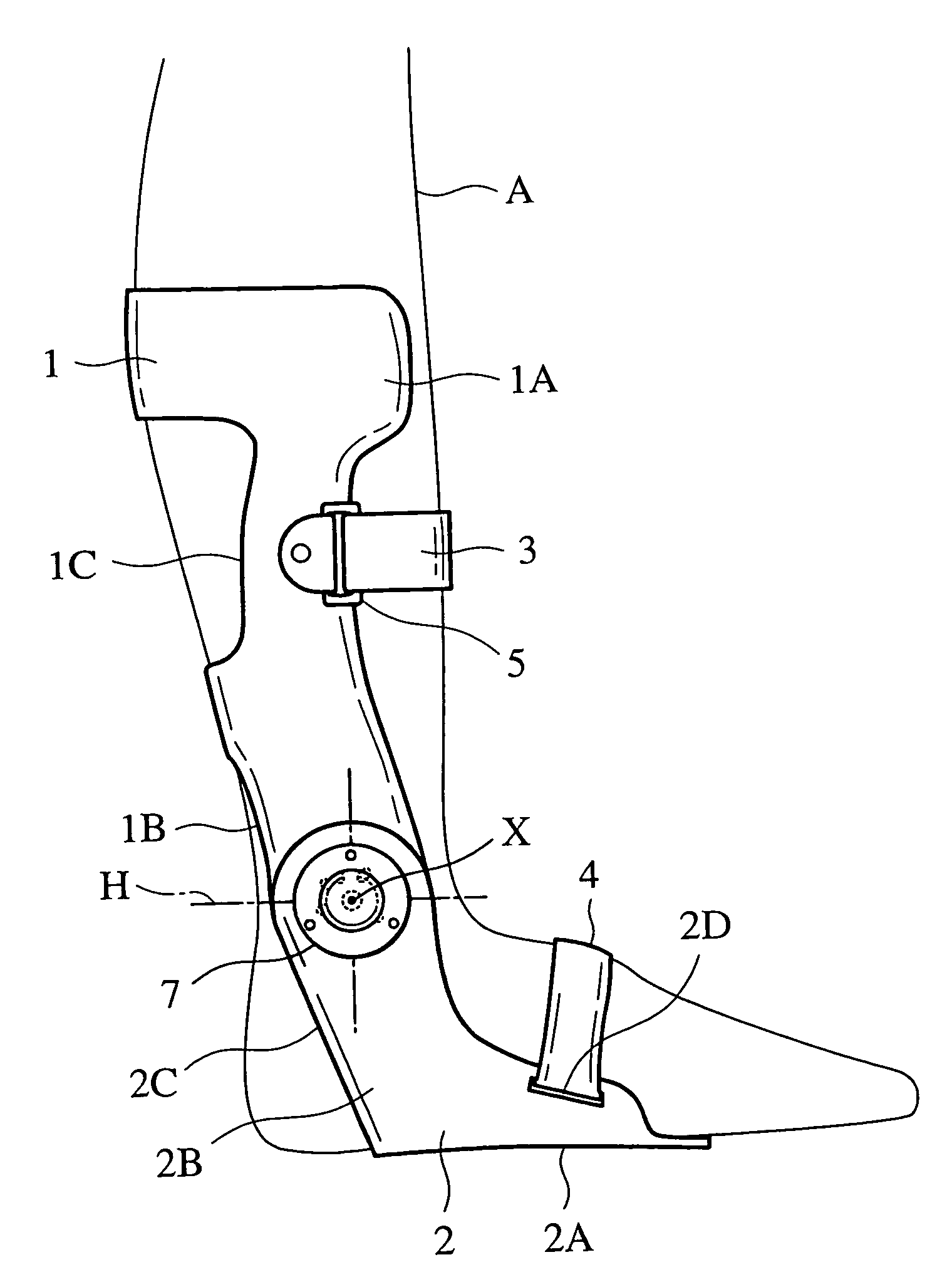
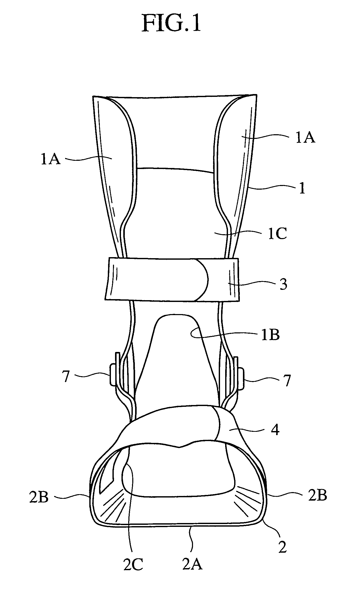
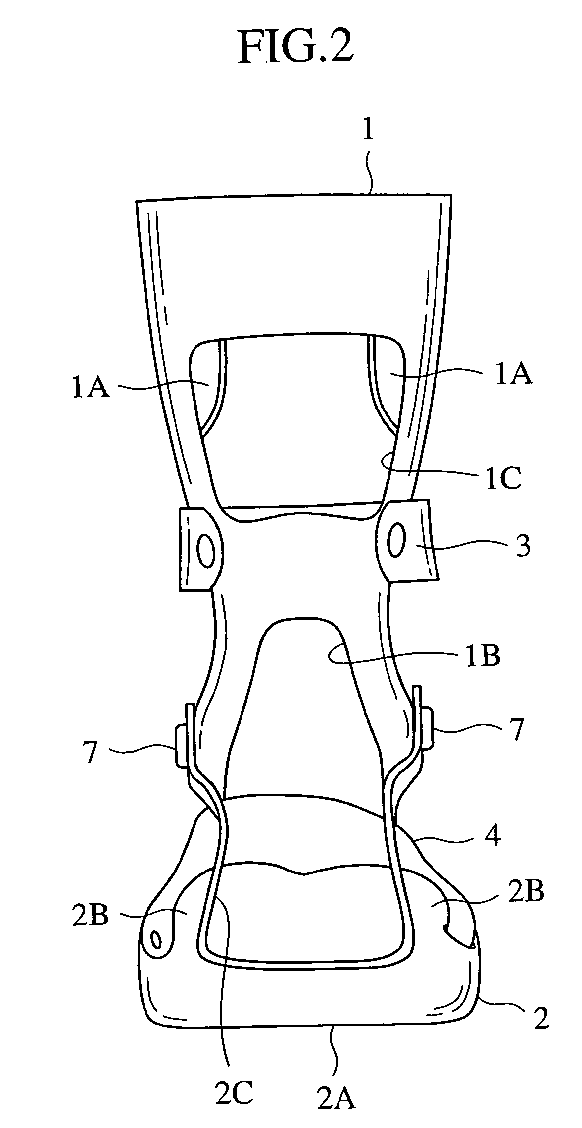
[0053]FIGS. 1 to 3 show a body orthosis according to a first embodiment of the present invention. This body orthosis includes two body protective members as main constitutional members. These two members are a facies posterior cruris cuff (leg protective plate) 1 provided with a pair of left and right flared portions 1A and 1A formed bent in a near circular-arc shape when seen from a plane to protect a calf in a rear surface of a shank, and extended forward in an upper end side to cover a part of the shank, and a sole plate 2 nearly U-shaped when seen from a front, provided with a loading portion 2A having a horizontal surface to load and support a foot (part below an ankle), and rising portions 2B and 2B rising from both left and right sides of the loading portion 2A. The facies posterior cruris cuff 1 and the sole plate 2 adjacent to each other in upper and lower directions are connected so as to be rotated around a horizontal axial center. A lower limb below a knee can be fixed t...

second embodiment

[0071]FIGS. 11A to 11C show a second embodiment of the present invention.

[0072]A body orthosis 20 includes a cuff 21 having a pair of left and right flared portions 21A and 21A for protecting a rear part of an upper arm portion, a front arm cuff 22 similarly having a pair of left and right flared portions 22A and 22A for protecting a rear part of a front arm portion. The body orthosis 20 is bent in a circular-arc shape. The cuffs 21 and 22 of the upper and front arm portions are connected to each other so as to be rotated around a horizontal axial center substantially from a cubital fossa to an elbow. In this case, the outer side member 7 and the inner member 6 are connected to each other by connecting members 25A and 25B respectively for the upper and front arm cuffs 21 and 22. Then, the two connecting members 25A and 25B are respectively fixed to the cuffs 21 and 22 by screws 29 or the like.

[0073]Moreover, by four belts 23A to 23D provided in the body orthosis 20, upper and front ...

third embodiment

[0076]FIGS. 12A to 12D show a body orthosis according to a third embodiment of the present invention.

[0077]FIG. 12A is a side view showing a body orthosis 30 of the embodiment. The body orthosis 30 includes a thigh cuff 31 having a pair of left and right flared portions 31A and 31A for protecting a rear part of a thigh portion, and a lower thigh cuff 32 similarly having a pair of left and right flared portions 32A and 32A for protecting a rear part of a lower thigh. The body orthosis 30 is bent in a circular-arc shape. The cuffs 31 and 32 for the thigh and lower thigh portions are connected to each other so as to be rotated around a horizontal axial center substantially from a knee fossa to a knee. In this case, the outer side member 7 and the inner member 6 are connected to each other by connecting members 37A and 37B respectively for the thigh and lower thigh cuffs 31 and 32. Then, the two connecting members 37A and 37B are respectively fixed to the cuffs 31 and 32 by screws 29 or...


PUM


Abstract

A body orthosis having a pair of body protective members adjacent to each other in a vertical direction, in which one of the body protective member 1 is constituted so as to rotate freely with respect to the other body protective member 2, the body orthosis including rotational load setting means 8 for setting a rotational load in one rotational direction of the rotatably constructed body protective member 2 larger than a rotational load in the other rotational direction.

Description

TECHNICAL FIELD[0001]The present invention relates to a body orthosis especially effective as a body corrective orthosis for talipes equinovarus, the body orthosis having a pair of body protective members adjacent to each other in a vertical direction, in which one of the body protective members is constituted so as to rotate around an axial center in a direction perpendicular to the adjacent direction thereof with respect to the other body protective member.BACKGROUND ART[0002]Talipes equinovarus (clubfoot) means a disorder of a walking function, which causes stumbling easily by stubbing a toe against the ground during walking. This is because inward bending of a foot directs its sole inward, and impossibility of controlling an ankle causes a tiptoe side of the foot (referred to toe, hereinafter) to droop downward.[0003]In order to prevent the stumbling during walking, a toe is corrected upward generally to prevent the drooping downward of the toe. Various types of body orthoses ha...

Claims


Application Information

Patent Timeline
IPC IPC(8): A61F5/00A61F5/01
CPCA61F5/0125A61F5/0127A61F5/013A61F2005/0174A61F2005/0167A61F2/66
Inventor MORINAKA, SHIGERU
Owner SHIYOMI PROSTHETIC MFG
Why Eureka
Try Eureka