

Multi-edge cutting head and an insert used therein
- Summary
- Abstract
- Description
- Claims
- Application Information
AI Technical Summary
Benefits of technology
Problems solved by technology
Method used
Image

Examples
Embodiment Construction
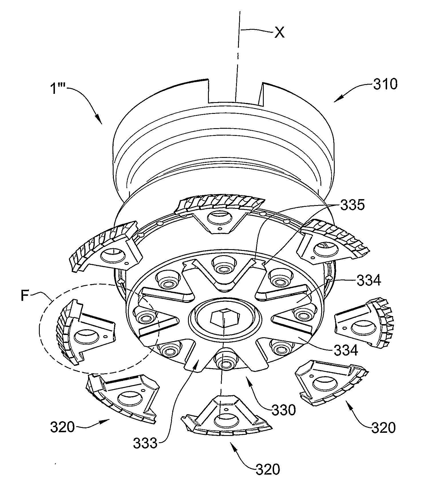
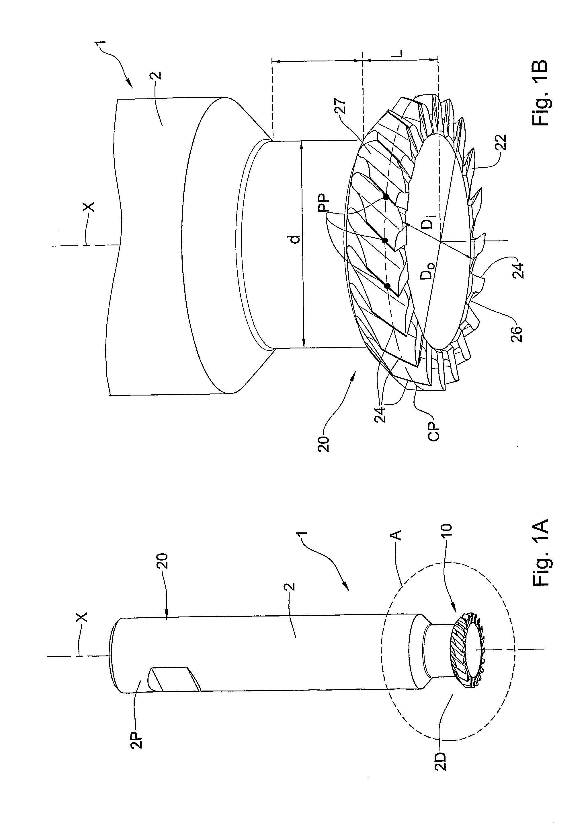
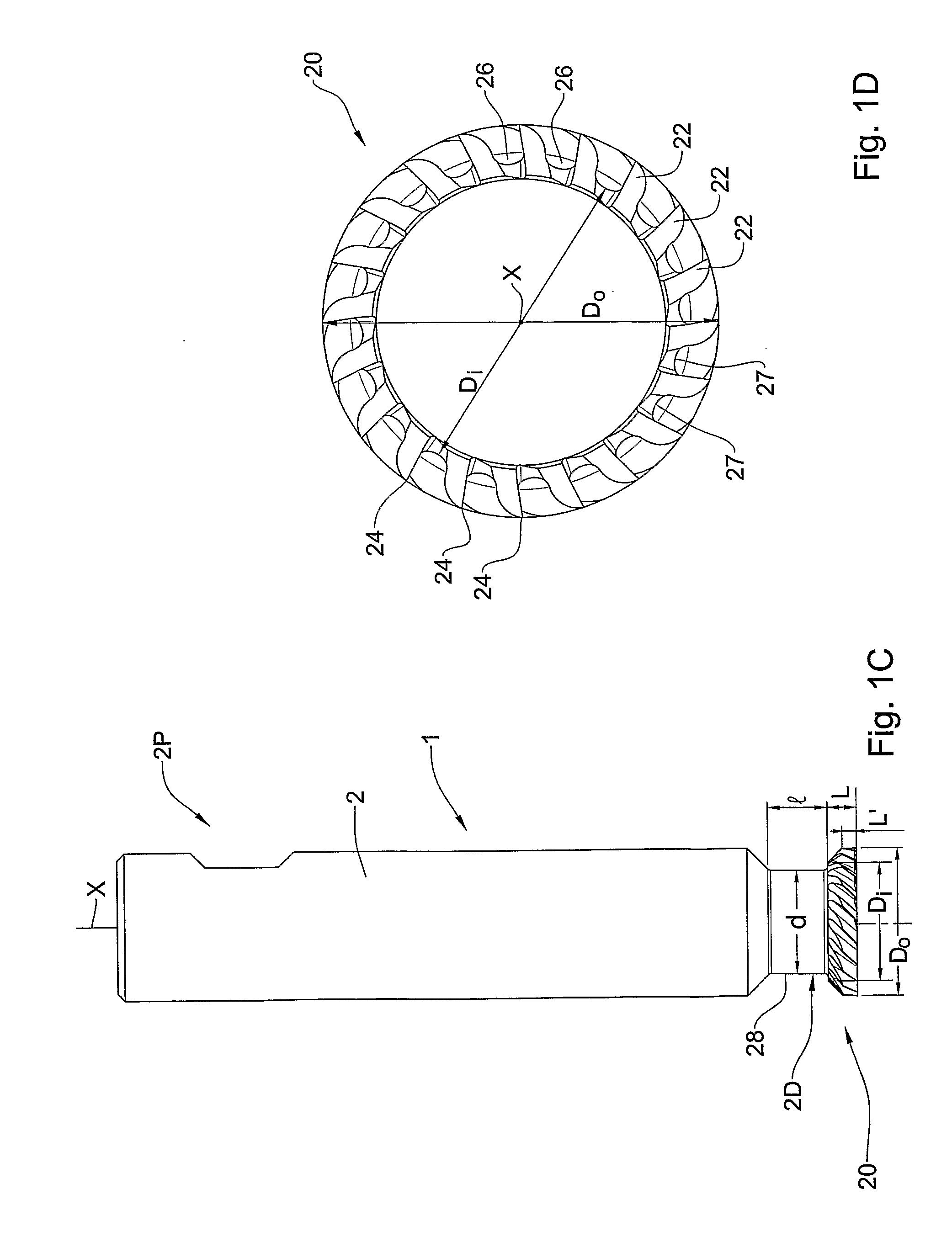
[0106]With reference to FIG. 1A, a cutting tool generally designated as 1 is shown comprising a body 2 extending along a central axis X, and having a proximal end 2P and a distal end 2D, formed with a mounting portion 10 and a cutting head 20 respectively.
[0107]The cutting head 20 of the cutting tool 1 is adapted for removing a thin layer of material from a workpiece (not shown) when coming in contact therewith during rotation of the cutting tool 1. The removal of the layer is achieved by the removal of chips from the surface of a workpiece, with the cutting tool 1 progressing laterally to the central axis X while revolving thereabout, and while in contact with said workpiece.
[0108]With particular reference to FIGS. 1B to 1D, the cutting head 20 is formed with a cutting portion having a plurality n of cutting teeth 22, each having a cutting edge 24. The cutting teeth 22 are equally spaced about the central axis X. Between each two adjacent cutting teeth 22, there is formed a chip ev...
PUM
| Property | Measurement | Unit |
|---|---|---|
| Angle | aaaaa | aaaaa |
| Angle | aaaaa | aaaaa |
| Angle | aaaaa | aaaaa |
Abstract
Description
Claims
Application Information