Electromagnetic switch for starter

a technology of electric switch and starter, which is applied in the direction of engine starter, machine/engine, magnetism body, etc., can solve the problems of increasing the size and weight of the terminal, difficulty in suppressing the vibration of the terminal, etc., and achieves the effect of improving the tolerance against vibration

Inactive Publication Date: 2009-08-04
DENSO CORP
View PDF17 Cites 27 Cited by
  • Summary
  • Abstract
  • Description
  • Claims
  • Application Information

AI Technical Summary

Benefits of technology

[0014]The present invention, which is made in view of the foregoing problem, has an object to provide an electromagnetic switch for a starter, the electromagnetic switch improving tolerance against a vibration imposed on a current-receiving terminal to an excitation coil arranged in the switch.
[0016]Therefore, if a vibration is imposed on the terminal, the vibration absorber operates to absorb the imposed vibration so as to prevent or suppress the vibration, resulting in that the tolerance of the terminal against the vibration can be improved, raising the durability of the electrometric switch.
[0019]As another aspect, the present invention provides an apparatus comprising an external connector allowing an electric current pass through from a power supply to the apparatus, and a vibration absorber configured to absorb a vibration imposed on the external connector, wherein in particular the external connector has the vibration absorber. Thus, a vibration imposed on the external connector is absorbed well by the vibration absorber with steadiness.

Problems solved by technology

In the aforementioned wiring structure for supplying the electric current to the excitation coil, however, there is a difficulty that a vibration of the terminal is not suppressed.
However, in such an enlarged or strengthened structure, various problems including increases in size and weight of the terminal will arise.

Method used


Image

  • Electromagnetic switch for starter
  • Electromagnetic switch for starter
  • Electromagnetic switch for starter

Examples


first modified embodiment

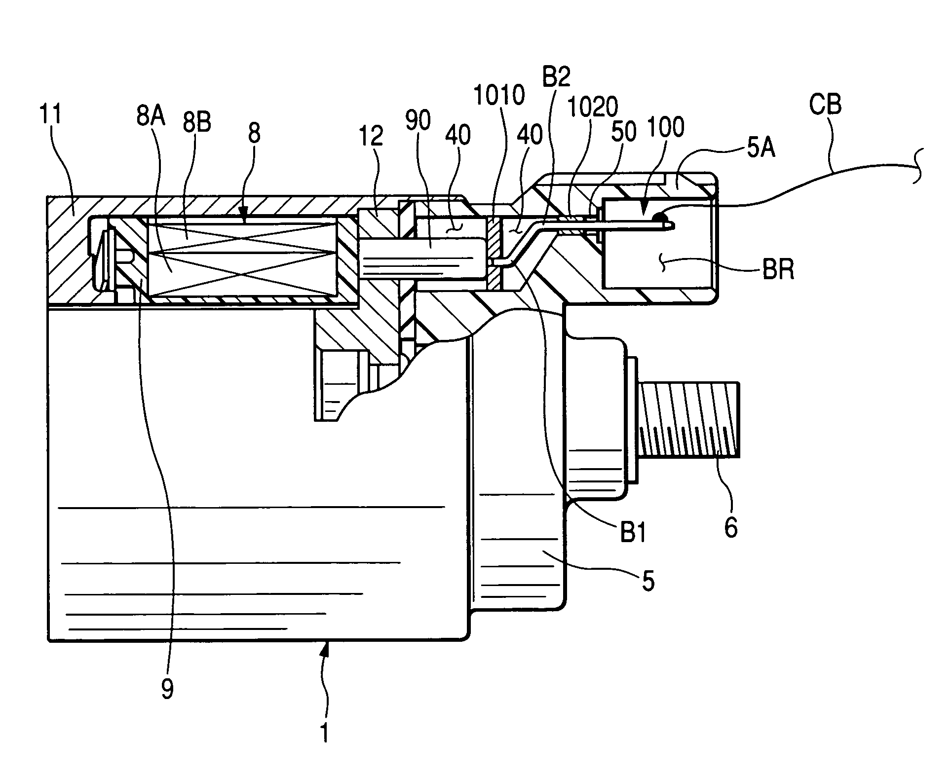
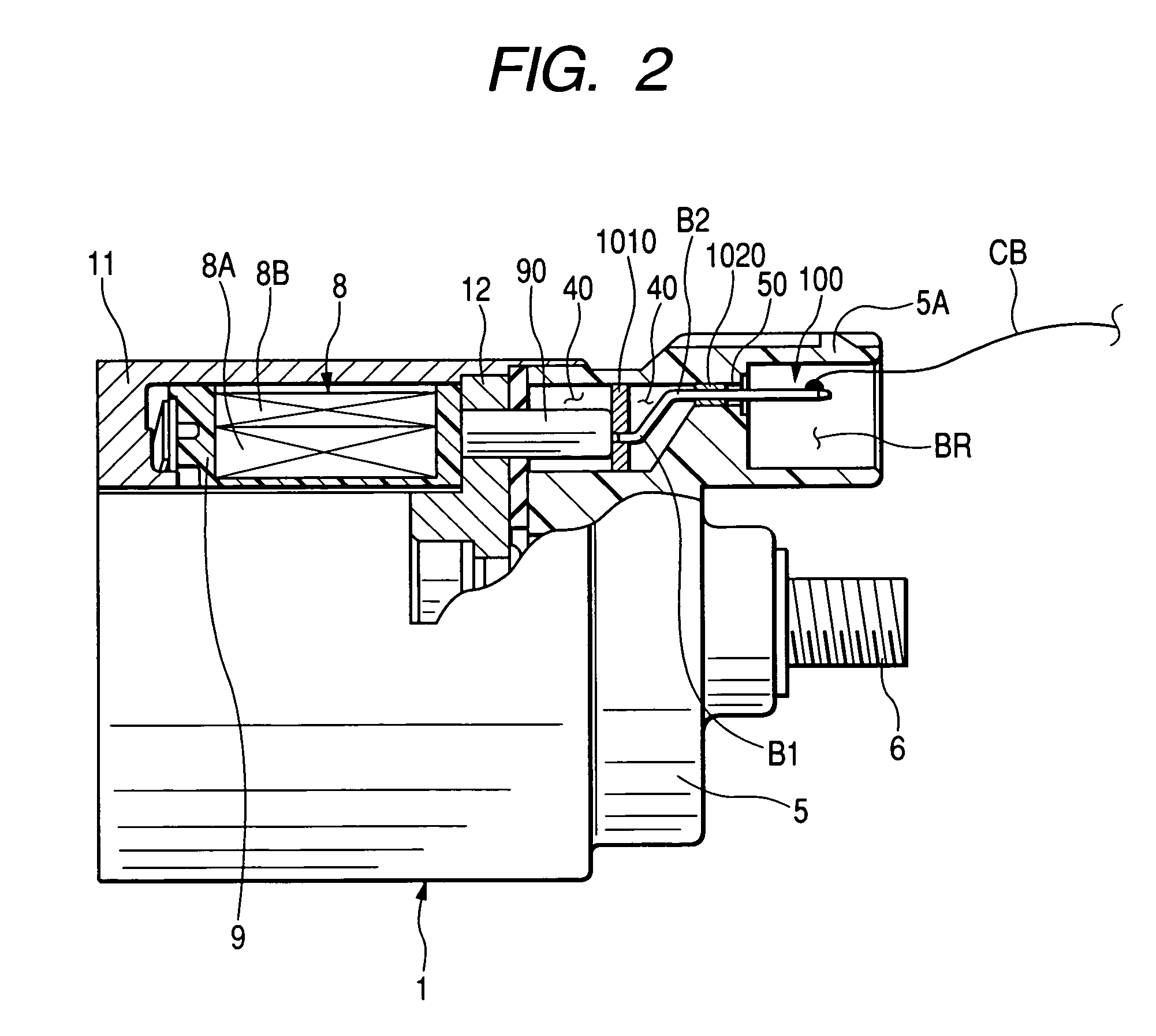
[0077]Referring to FIG. 6, a first modified embodiment will now be described. This first modified embodiment relates to the radial position of the connection port 5A formed to protrude from the molded cover 5. In the configuration shown in FIG. 2, the bent portion BT of the terminal 100 is formed such that the bent portion BT is directed to extend outwardly in the radial direction of the molded cover 5, thus the radial position of the connection port 5A becomes higher depending on the slope of the intermediate segment 102 of the bent portion BT. But this is not a definitive list about the radial position of the connection port 5A.

[0078]For example, as shown in FIG. 6, the intermediate segment 102 may be located so as to have a descendent slope in the radial direction as the position on the terminal 100 goes toward the outside in the axial direction. This arrangement allows the connection port 5A to be positioned closer to the radial center position of the molded cover 5. Hence, comp...


PUM


Abstract

An electromagnetic switch for a starter comprises a current-supply terminal and a vibration absorber configured to absorb vibration imposed on the terminal. The terminal is provided so that one end of the terminal is tightly attached to the switch, and the other end is connected to a cable which supplies electric current to the switch. One end of the terminal is tightly attached to a bobbin wound by an excitation coil to which the current is supplied and the other end protrudes through a molded cover outward to be connected to the cable at a connection port formed in the molded cover. The vibration absorber is, for example, a bent portion of the terminal formed integrally with the terminal itself. One or more flexible members are attached to the terminal to support the terminal within the electromagnetic switch and to seal inner spaces between the terminal and the switch.

Description

CROSS REFERENCE TO RELATED APPLICATION[0001]The present application is based on Japanese Patent Application No. 2004-368133 filed on Dec. 20 2004, the disclosure of which is incorporated herein by reference.BACKGROUND OF THE INVENTION[0002]1. Technical Field of the Invention[0003]The invention relates to an electromagnetic switch used in a starter for starting an internal combustion engine mounted on a vehicle and particularly to the electromagnetic switch with a pull-out structure of a lead wiring which supplies an electric current to a solenoid coil incorporated in the switch.[0004]2. Related Art[0005]In general, a combustion engine installed in the vehicle is stared by a dedicated apparatus, called a starter. This starter incorporates an electromagnetic switch, which is turned on whenever the combustion engine is started. A conventional starter switch has a resinous molded cover which encloses a movable contact and a pair of stationary contacts. The conventional starter switch al...

Claims


Application Information

Patent Timeline
Patent Type & Authority Patents(United States)
IPC IPC(8): H01H51/08
CPCF02N11/00H01H50/443H01H50/14F02N15/063H01H50/546H01H50/22
Inventor HIRABAYASHI, TAKASHI
Owner DENSO CORP
Why Eureka
Try Eureka