Laser scanning apparatus with improved optical features

a scanning apparatus and optical feature technology, applied in the direction of mechanical measuring arrangements, measuring devices, instruments, etc., can solve the problems of not providing information by itself as to the extent of straightening to be accomplished, the casting is not thermally stable, and the apparatus suffers from a number of problems and limitations, so as to reduce the number of major adjustments, facilitate and improve the accuracy of alignment mechanisms

Inactive Publication Date: 2009-08-04
VEHICLE SERVICE GROUP LLC
View PDF18 Cites 14 Cited by
  • Summary
  • Abstract
  • Description
  • Claims
  • Application Information

AI Technical Summary

Benefits of technology

[0012]The present invention provides an improved laser scanning apparatus for use in conjunction with a plurality of coded targets suspended from, or in an otherwise known relationship to known reference points on a vehicle, to determine three dimensional spatial coordinates defining the actual positions of the targets, and to compare such determined positions with manufacturer-provided specification values in order to identify deformation in the frame or unibody of the vehicle. The present invention provides component isolation using a mounting plate and isolation mounts; signal collection using an independent synchronization circuit that uses a fiber optic cable for signal collection; component alignment using easier and more reliable alignment mechanisms; and data collection and processing using onboard data averaging and filtering. It will be understood that any one or more of these features may be incorporated into substantially any prior art or yet to be invented laser scanning apparatus that may benefit therefrom.
[0013]More specifically, the present invention includes mounting the optical components on a mounting plate which is isolated from cast support structures by isolation mounts, and thereby avoids problems arising from mounting the optical components directly on the castings.
[0014]Furthermore, the present invention includes providing a second independent synchronization circuit to allow for optimizing each synchronization circuit for a particular type of reflection signal. Also, at least the second synchronization circuit, and possibly both synchronization circuits, is provided with a fiber optic cable for signal collection. The combination of circuit optimization and fiber optic cable avoids problems arising from using the same detection circuitry and optics for both types of signals.
[0015]Additionally, the present invention includes reducing the number of major adjustments that may need to be made in order to align the optical components. More specifically, a limited number of strategically placed jack screws, ball joints, and springs, are used to allow for adjusting the lasers and the mirrors, thereby avoiding problems arising from difficult and unreliable alignment methods.
[0016]Additionally, the present invention includes synthesizing all available data prior to communicating it to the associated microprocessor, thereby avoiding limitations arising from a relatively slow data communication rate.

Problems solved by technology

Repairing accidental damage to these vehicles often involves straightening their frames and reshaping or replacing body panels.
While such straightening machines are highly effective, they do not by themselves provide information as to the extent of straightening to be accomplished.
Unfortunately, this apparatus suffers from a number of problems and limitations.
This creates problems for several reasons, including that the castings are not thermally stable, the castings are subject to warping when bolted together, and shock to and vibration of the castings is transmitted directly to the optical components.
As a result, the apparatus is susceptible to thermal cycling, misalignment, shock, and vibration, any of which can adversely affect accuracy.
Using the same circuitry and optics to detect both the high-intensity sync signal and the low-intensity target reflection signals creates problems due to compromises made in the detection circuitry and optics to handle both types of signals.
The prior art alignment methods can be difficult to perform and unreliable.
However, the mirrors rotate and generate data at approximately six revolutions per second, and so the excess data is discarded and lost.

Method used


Image

  • Laser scanning apparatus with improved optical features
  • Laser scanning apparatus with improved optical features
  • Laser scanning apparatus with improved optical features

Examples


Embodiment Construction

, below.

BRIEF DESCRIPTION OF THE DRAWINGS

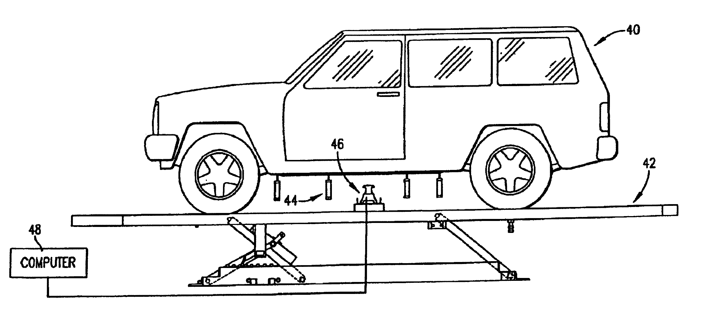
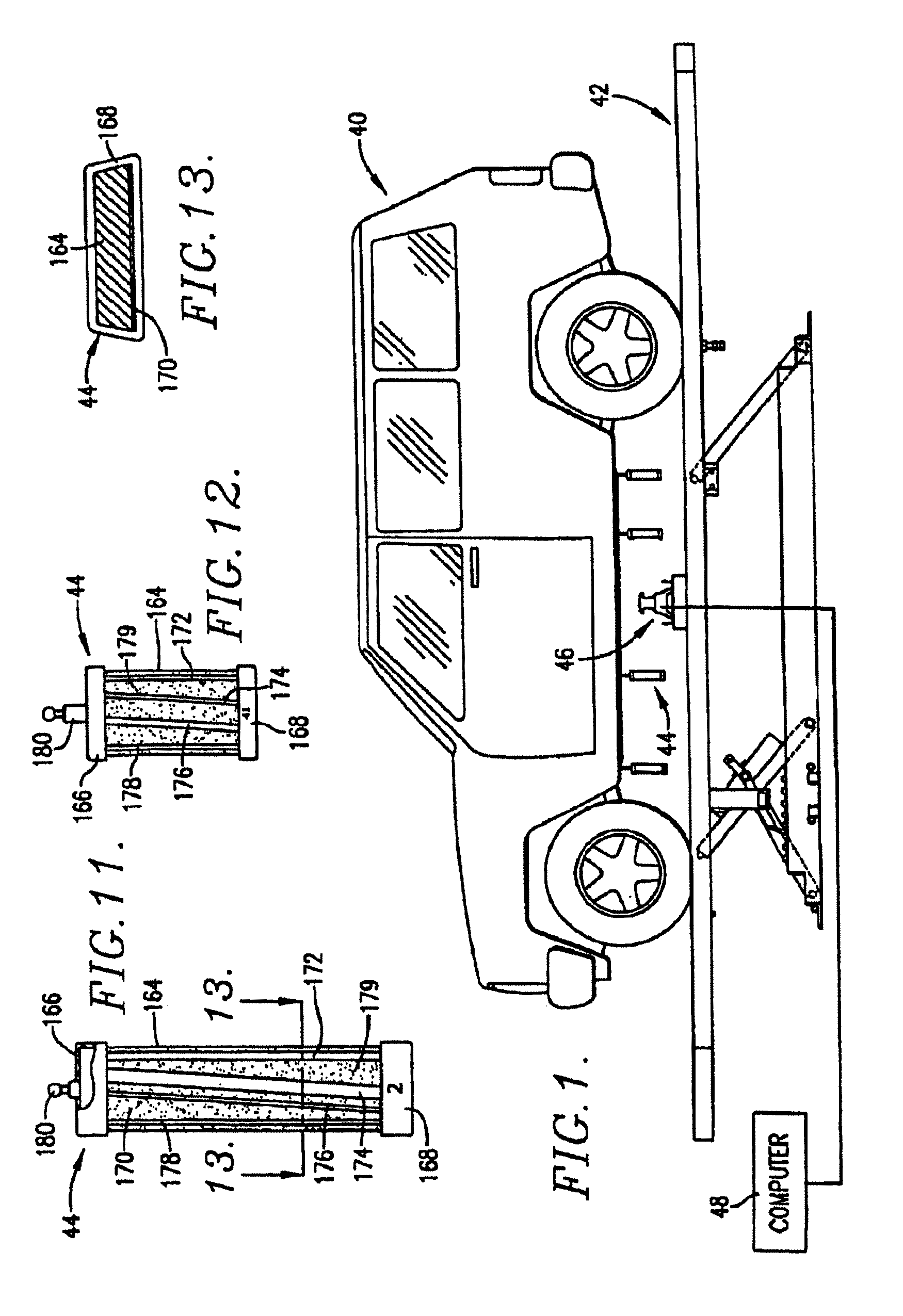
[0018]FIG. 1 is a side elevational view of a vehicle having coded reflective targets suspended from predetermined locations on the vehicle, and with a laser scanning apparatus disposed below the vehicle and in an orientation for scanning the depending targets;

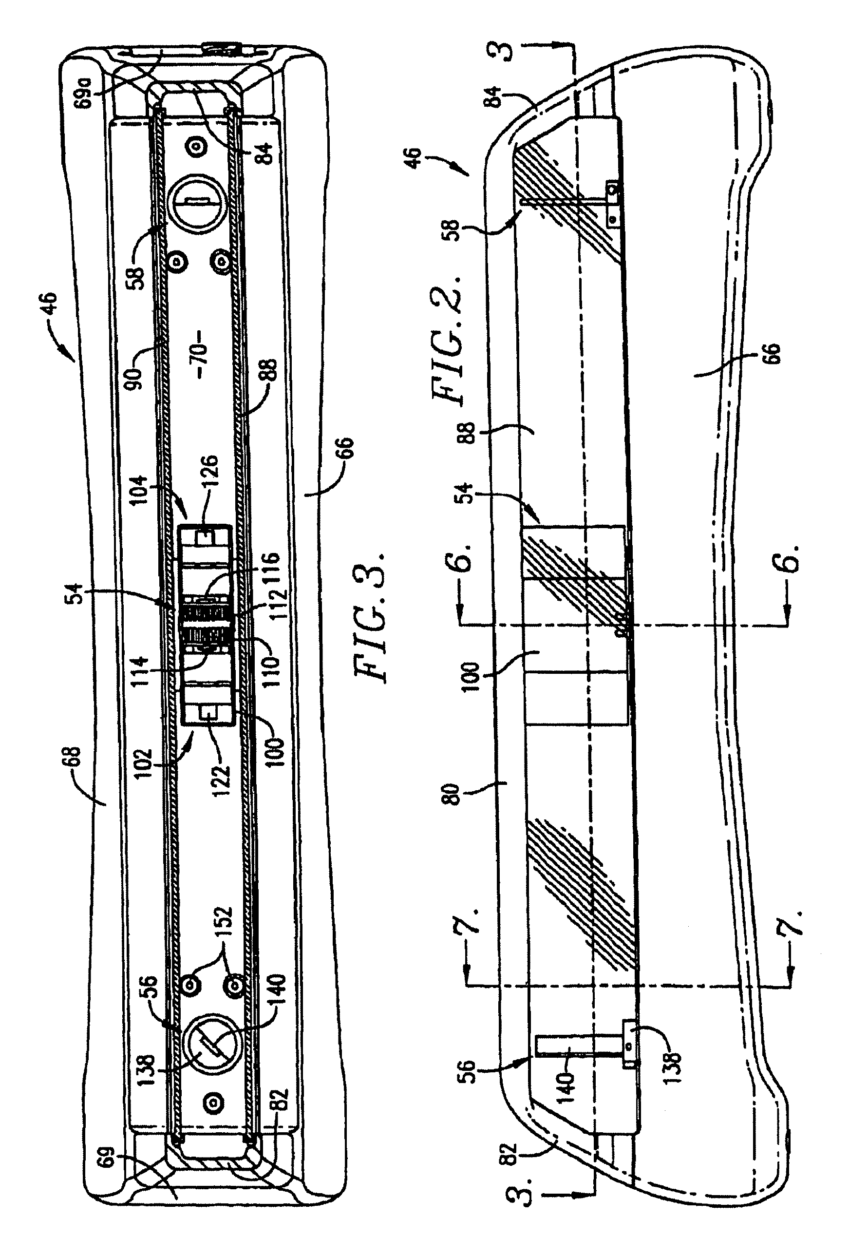
[0019]FIG. 2 is a front elevational view of a laser scanning apparatus;

[0020]FIG. 3 is a sectional view taken along line 3-3 of FIG. 2 and depicting further details of the internal construction of the laser scanning apparatus;

[0021]FIG. 4 is a vertical sectional view of the laser scanning apparatus;

[0022]FIG. 5 is a bottom view of the laser scanning apparatus, with the bottom cover plate removed;

[0023]FIG. 6 is a vertical sectional view taken along line 6-6 of FIG. 2 and depicting components of the laser assembly of the laser scanning apparatus;

[0024]FIG. 7 is a vertical sectional view taken along line 7-7 of FIG. 2 and illustrating in detail the construction of the mirror assemblies of ...


PUM


Abstract

Laser scanners are used for determining deformation in vehicle bodies and the like, using a laser scanning apparatus in conjunction with a plurality of coded targets suspended from (or in known relationship to) known reference points on the vehicle to calculate three dimensional spatial coordinates defining the actual positions of the targets, and to compare such calculated positions with manufacturer-provided specification values. The present invention provides improved signal collection through the use of an independent synchronization circuit that uses a fiber optic cable for signal collection; improved component isolation through the use of a mounting plate and isolation mounts; improved component alignment through the use of easier and more reliable alignment mechanisms; and improved data collection and processing through the use of onboard data averaging and filtering.

Description

RELATED APPLICATIONS[0001]The present U.S. non-provisional patent application claims priority benefit of an earlier-filed co-pending U.S. provisional patent application titled “Laser Scanner with Improved Optical Features”, Ser. No. 60 / 723,731, filed Oct. 5, 2005. The identified provisional patent application is hereby incorporated by reference into the present non-provisional patent application.BACKGROUND OF THE INVENTION[0002]1. Field of the Invention[0003]The present invention relates to devices and methods for determining deformation in vehicle frames or unibodies and the like, using a laser scanning apparatus in conjunction with a plurality of coded targets suspended from, or in an otherwise known relationship with, known reference points on the vehicle to determine three dimensional spatial coordinates defining the actual positions of the targets, and to compare these determined positions with manufacturer-provided specification values for the reference points.[0004]2. Backgro...

Claims


Application Information

Patent Timeline
Patent Type & Authority Patents(United States)
IPC IPC(8): G01B11/26
CPCG01B5/0025
Inventor FLANNIGAN, WILLIAM CLAYCAMPBELL, JAMES BRETT
Owner VEHICLE SERVICE GROUP LLC
Why Eureka
Try Eureka