Compton camera configuration and imaging method

a technology of compton camera and configuration method, applied in the direction of optical radiation measurement, radiation control device, instruments, etc., can solve problems such as unoptimized parameters

Inactive Publication Date: 2009-08-11
SMITH BRUCE D
View PDF27 Cites 24 Cited by
  • Summary
  • Abstract
  • Description
  • Claims
  • Application Information

AI Technical Summary

Problems solved by technology

But those paradigms are not optimal if the two Compton data models described in the 2005 paper are used to reconstruct.

Method used


Image

  • Compton camera configuration and imaging method
  • Compton camera configuration and imaging method
  • Compton camera configuration and imaging method

Examples


Embodiment Construction

[0042]Finding the Conical Surface Region From Which a Detected Photon Originated

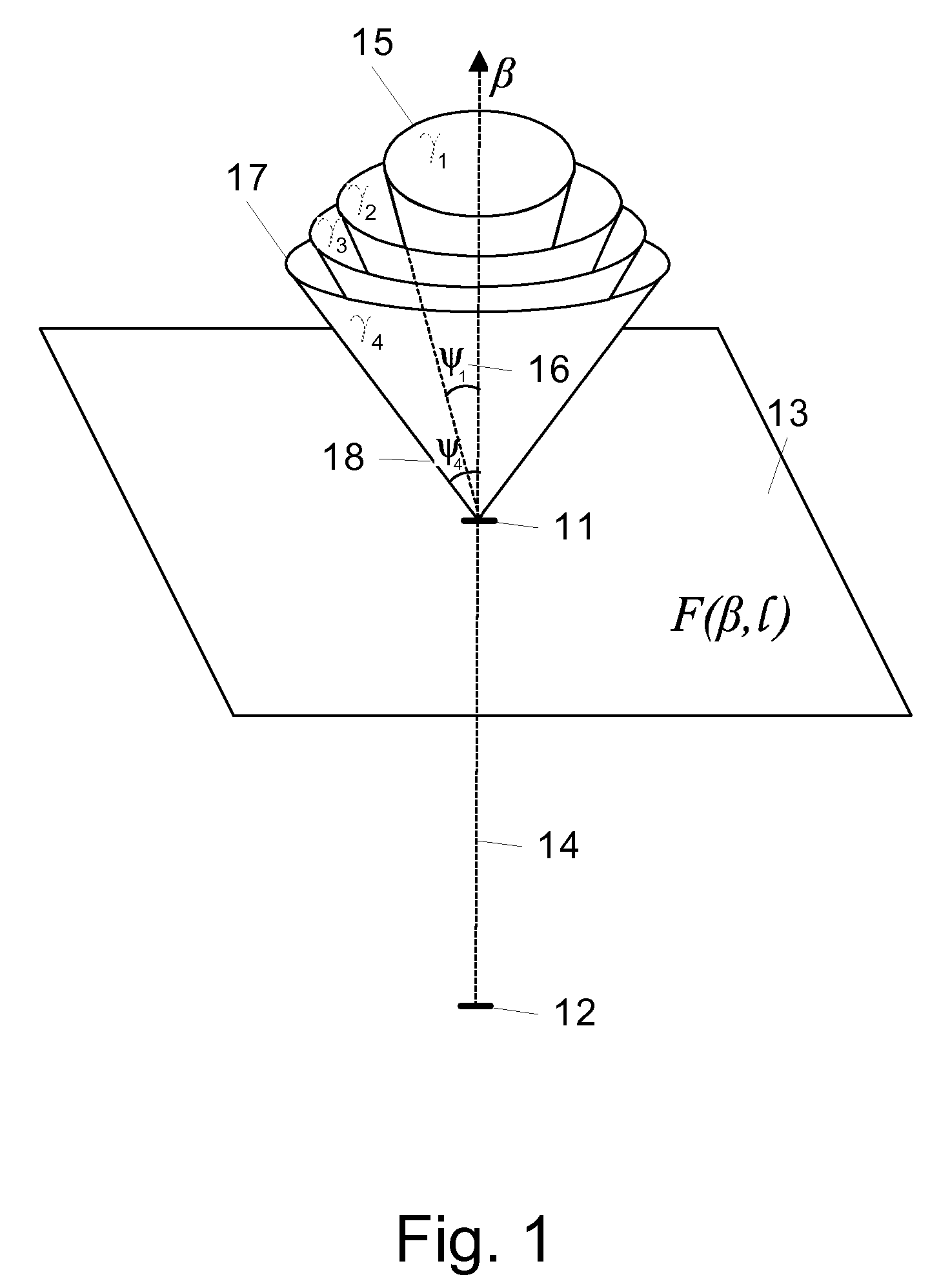
[0043]FIG. 1 illustrates how for a pair of first and second detector elements 11 and 12 in a Compton camera, there is a cone of origin associated with each photon that is counted, the cone having an apex at the first detector element 11, an axis of symmetry 14 collinear with the line connecting the first and second detector elements 11 and 12, and a conical angle 16, 18, etc., that corresponds to the difference between the pre- and post-scatter wavelengths of the photon.

[0044]If it is known that a photon has interacted with a first detector element 11, and is scattered (deflected) by the first detector element 11 toward a second detector element 12, then it is known that the photon originated from a point that lies on the surface of a cone whose apex is at the first detector element 11 and whose axis of symmetry 14 is the line containing first and second detector elements 11 and 12. If the pre- and post-...


PUM


Abstract

An approach for the selection of Compton camera shapes, configurations, positions, orientations, trajectory paths, and detector element sets is provided for collecting data for analysis using the surface integral and integral-of-line-integral methods of reconstruction Compton data. Methods are introduced for (1) selecting one or more imaging lines through a radioactive distribution for which approximations of integrals of radioactivity are to be derived, (2) selecting and using Compton camera relative positions, relative orientations, and detector element sets that “correspond to” the selected imaging lines to collect the needed data; and (3) deriving approximations of integrals of radioactivity along those imaging lines. This methodological approach is used to reconstruct line integrals, cross-sections, local volumes, parallel projections, and cone-beam projections of radioactive distributions.

Description

RELATED APPLICATIONS[0001]This application claims the benefit of, and hereby incorporates by reference, my U.S. provisional patent application no. 60 / 894,478, entitled “Paradigms for Designing Compton Cameras and Telescopes and Reconstruction Methods for Redundant Data Sets,” and filed on Mar. 13, 2007.FIELD OF THE INVENTION[0002]This invention relates generally to imaging methods using a Compton camera, and more particularly to the selection of Compton camera shapes, configurations, positions, orientations, trajectory paths, and detector element sets to collect data for analysis using the imaging methods.BACKGROUND OF THE INVENTION[0003]Compton's Scattering Law[0004]In 1923, Arthur Holly Compton observed that X-ray and gamma ray photons frequently scatter and lose energy (and gain wavelength) when they interact with electrons in matter. This phenomenon—which demonstrates that light has particle, as well as wave properties—has come to be known as Compton scattering. Observations hav...

Claims


Application Information

Patent Timeline
Patent Type & Authority Patents(United States)
IPC IPC(8): G01J1/00G01T1/00
CPCG01T1/1647G01T1/29A61B6/027
Inventor SMITH, BRUCE D.
Owner SMITH BRUCE D
Why Eureka
Try Eureka