Systems for doppler tracking using photonic mixing detectors

a detector and photonic technology, applied in the field of laser detection and ranging, can solve the problems of not always advantageous use, more expensive and difficult to design and manufacture focal plane arrays and their readout integrated circuits with such high bandwidths compared to lower bandwidth arrays, and add a lot of additional complexity to the system

Inactive Publication Date: 2009-08-11
US SEC THE ARMY THE
View PDF14 Cites 28 Cited by
  • Summary
  • Abstract
  • Description
  • Claims
  • Application Information

AI Technical Summary

Problems solved by technology

While such high bandwidth amplifiers exist, it is not always advantageous to use them due to their inherently higher noise properties.
In addition, it is more expensive and more difficult to design and manufacture focal plane arrays and their readout integrated circuits with such high bandwidths compared to lower bandwidth arrays.
Additional architectures have been devised which provide an individual local oscillator signal and acousto-optic modulator for each detector element in an array, but this adds a lot of additional complexity to the system, and can become cumbersome, and expensive to implement for reasonable size arrays.

Method used


Image

  • Systems for doppler tracking using photonic mixing detectors
  • Systems for doppler tracking using photonic mixing detectors
  • Systems for doppler tracking using photonic mixing detectors

Examples


Embodiment Construction

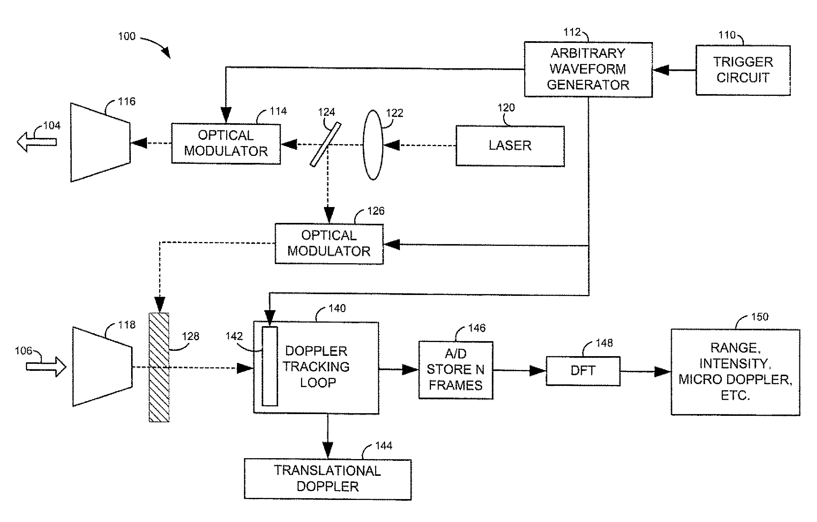
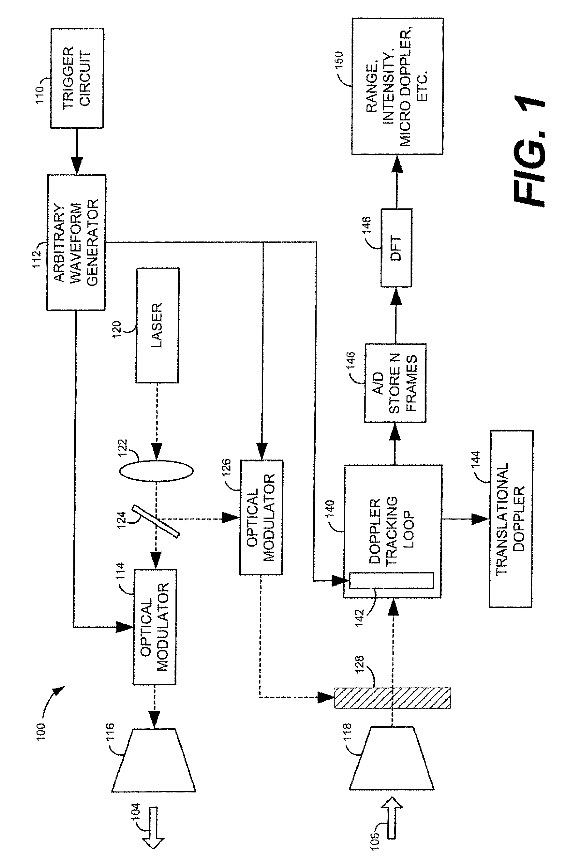
[0017]This disclosure relates to various embodiments of laser detection and ranging (LADAR) systems. Several embodiments are described below with reference to FIGS. 1-8. As an introductory matter, however, the basic architecture, operation, and functionality of an exemplary, non-limiting embodiment of a LADAR system will be briefly described. In general, the LADAR system operates by modulating a light signal with a known waveform and transmitting the modulated light signal toward a target. A portion of the transmitted laser intensity may be reflected from the target back toward the LADAR system and received by a sensor. The received light signal, which contains the original transmitted laser modulation, is delayed in time because of the long travel path from the transmitter to the target and back to the receiver and the optical carrier and modulation signal is shifted by the target velocity due to the Doppler Effect.

[0018]The LADAR system images the target by detecting various types...


PUM


Abstract

Ladar systems are provided. An exemplary ladar system includes a waveform generator for generating an arbitrary waveform, a laser for transmitting a modulated light signal toward a target, and a Doppler tracking loop for tracking the Doppler frequency shift between the transmitted light signal and a received reflected light signal.

Description

GOVERNMENT INTEREST[0001]The invention described herein may he manufactured, used, and licensed by or for the United States Government.CROSS-REFERENCE TO RELATED APPLICATIONS[0002]This application is related to U.S. patent application Ser. No. 10 / 183,536, filed Jun. 28, 2002, now U.S. Pat. No. 6,844,924 issued Jan. 18, 2005.TECHNICAL FIELD[0003]The invention generally relates to laser detection and ranging.DESCRIPTION OF THE RELATED ART[0004]For a typical optical heterodyne receiver, the return signal and the optical local oscillator signal are both directed onto an optical detector. Both signals are optically mixed with each other and the phase and frequency difference between the optical signals, as well as that of any modulation waveform applied to the optical signals, is converted from an optical to electrical signal by the optical detector. The optical fields can be represented simply as,E(t)signal=Asignal cos(ωsignalt+φsignal), E(t)LO=ALO cos(ωLOt)  (1)where we have associated...

Claims


Application Information

Patent Timeline
Patent Type & Authority Patents(United States)
IPC IPC(8): G01C3/08
CPCG01S7/491G01S17/58G01S17/02G01S7/4912
Inventor RUFF, WILLIAM CHARLESREDMAN, BRIAN C.STANN, BARRY LEE
Owner US SEC THE ARMY THE
Why Eureka
Try Eureka