Inner focusing zoom lens barrel

a zoom lens and barrel technology, applied in the field of zoom lens barrels, can solve the problems of varying the focal length, difficult to ensure a sufficient displacement of the focusing lens, and the drawback of the zoom lens that its outer diameter cannot be reduced further, so as to achieve smooth zooming and focusing operations, good cam configuration, and sufficient performance

Inactive Publication Date: 2009-08-11
TAMRON
View PDF6 Cites 0 Cited by
  • Summary
  • Abstract
  • Description
  • Claims
  • Application Information

AI Technical Summary

Benefits of technology

[0019]The inner focusing zoom lens barrel according to the present invention effectively makes a difference to a barrel arrangement so that smooth zooming and focusing operations can be conducted by virtue of its well-balanced cam configurations.
[0020]The inner focusing zoom lens barrel according to the present invention also effectively makes a difference to the barrel arrangement so that sufficient performances at the minimum object distance is attained while a focal distance is inhibited from varying throughout the entire zoom range, and the barrel has its outer diameter reduced.
[0021]The inner focusing zoom lens barrel according to the present invention further effectively makes a difference to the barrel arrangement so that attained are reduced restrictions imposed on configurations and positions of guiding cams, a greater overlapping segment where a linear-shuttle barrel is superposed on a fixed barrel for the tele-photo shooting, and an enhanced stability.

Problems solved by technology

In some high power inner focusing zoom lens, a displacement of a focusing lens during the photographing at the minimum object distance is greatly varied depending upon a zoom ratio, and hence, even if an attempt to enhance a photographing performance at the minimum object distance within a single stroke of focusing cams is successful in one of zooming ranges, this resultantly causes the displacement of the focusing lens being elongated in the remaining zoom ranges, which brings about the so-called “varying focal” length.
This causes a difficulty in ensuring a sufficiently balanced cam configuration to conduct a smooth zooming-focusing transition, resultantly necessitating to alter a rotation angle of the focusing cams or to compensate for transforming motion by the focusing cam.
However, it is still hard to ensure a sufficient displacement of the focusing lens to enhance the photographing performance at the minimum object distance and / or to inhibit from varying a focal length throughout the entire zoom range.
Some other prior art zoom lens of high power not more than ×5 is of five-layer assembly where a first cam barrel is disposed inside a fixed barrel while a second cam barrel, a linear-shuttle barrel, and, a third cam barrel are located outside the fixed barrel and such a zoom lens has a drawback that its outer diameter cannot be reduced any further.
With this mechanical design where the focusing lens is linearly displaced during the zooming, however, a fixed corrected displacement is applied in any of the zooming ranges, and this fixed corrected displacement makes it inappropriate to further shorten the minimum object distance in any of the zooming ranges for the high power zoom lens.
Additionally, the high power zoom lens is also of five-layer assembly where first and second cam barrels, a linear-shuttle barrel, and a third cam barrel are disposed outside a fixed barrel, and such a zoom lens is disadvantageous in that its outer diameter cannot be reduced any further.
Especially, for attaining a more enhanced zoom ratio, an axial displacement of third and fourth lens groups are to be greater, but it is hard to implement a well-balanced disposition of the guiding cams for these lens groups to be confined within the axial dimension available in the first cam barrel 16.

Method used


Image

  • Inner focusing zoom lens barrel
  • Inner focusing zoom lens barrel
  • Inner focusing zoom lens barrel

Examples


Embodiment Construction

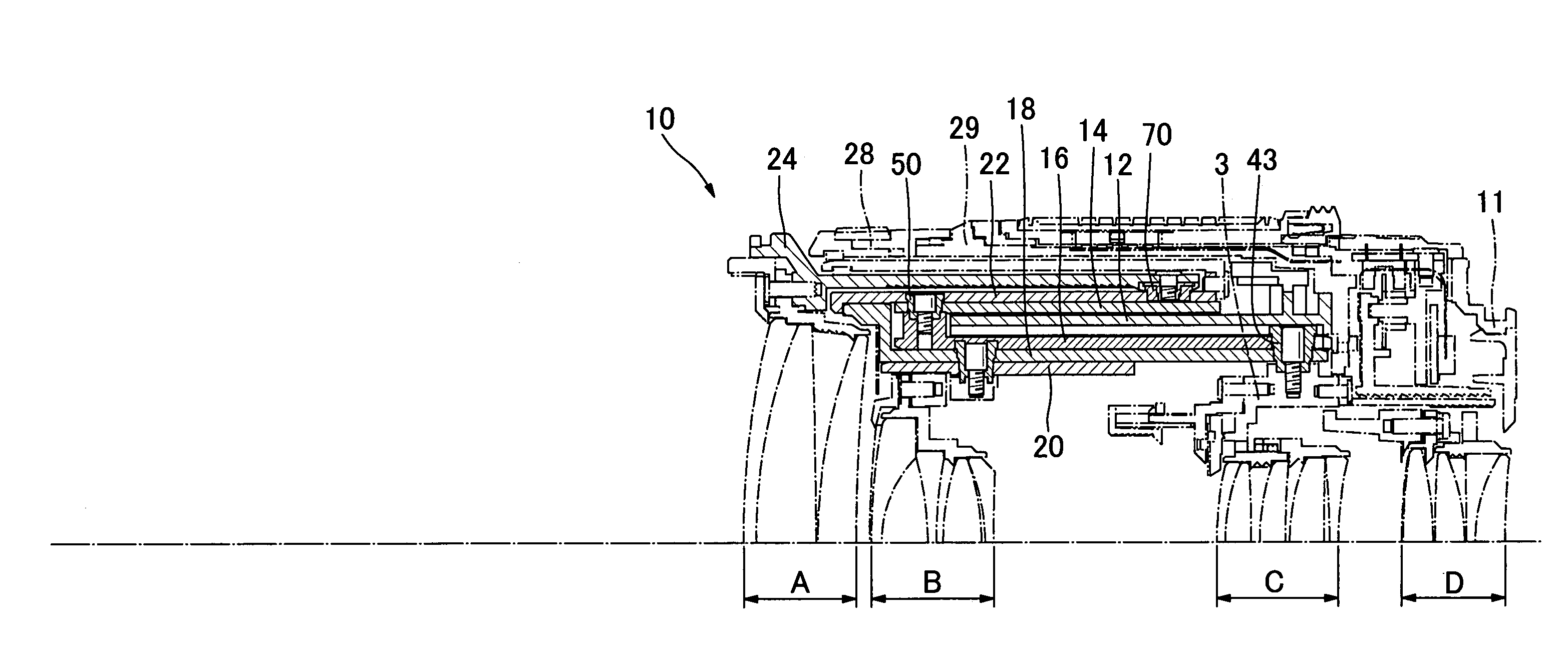
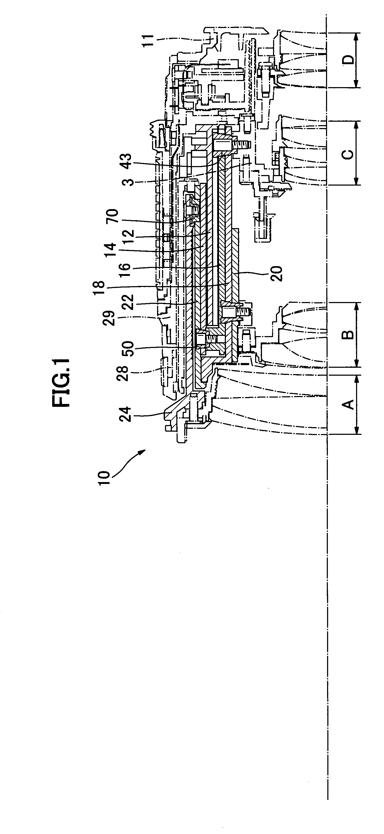
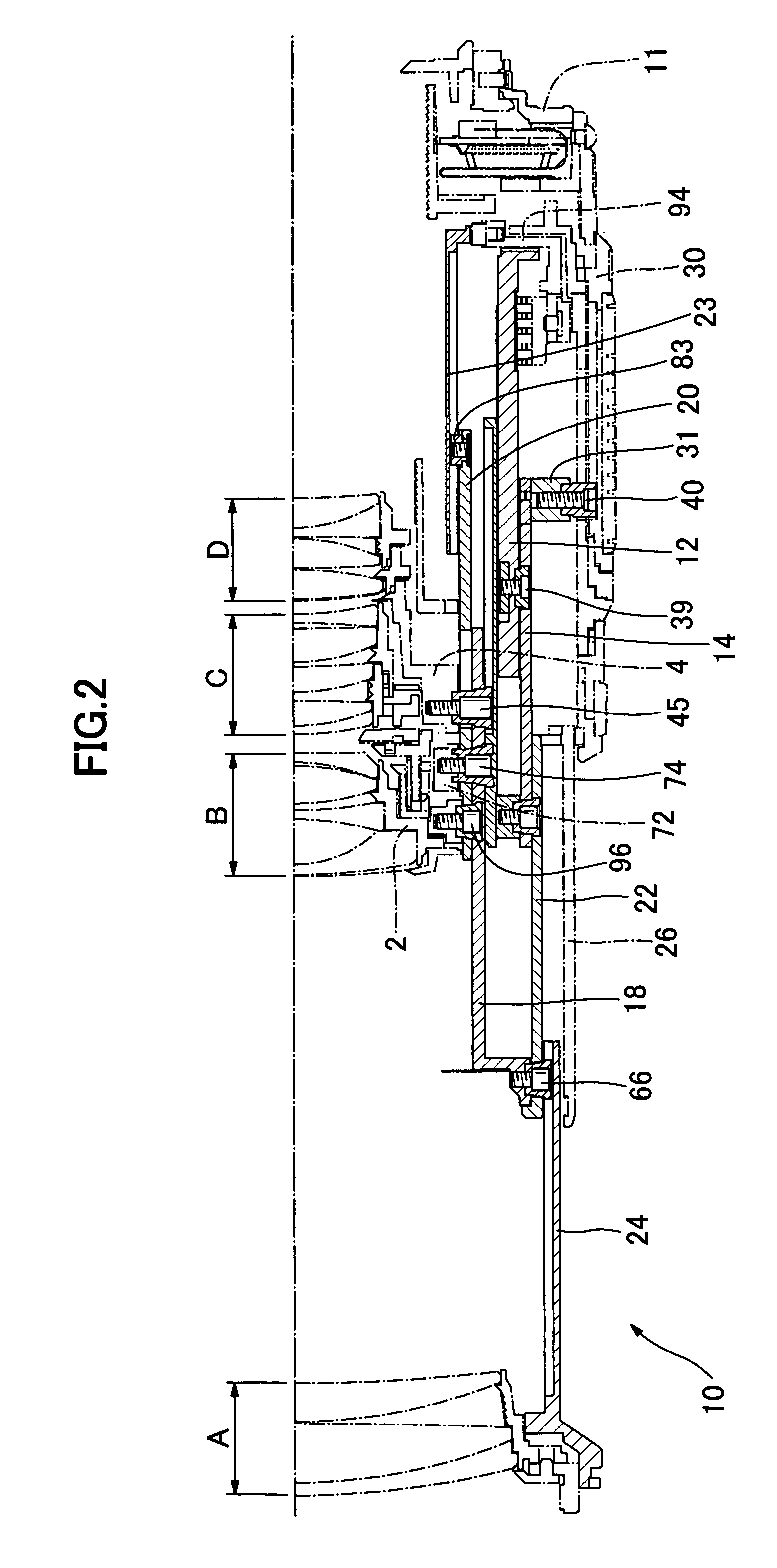
[0033]The best mode of an inner focusing zoom lens barrel according to the present invention will now be described in conjunction with the accompanying drawings.

[0034]An inner focusing zoom lens barrel 10 having a focal length of 18 mm to 250 mm houses a first lens group A (focal length of +95.5 mm), a second lens group B (focal length of −12.7 mm), a third lens group C (focal length of +43.7 mm), and a fourth lens group D (focal length of +46.2 mm), as shown in FIGS. 1 and 2. The zoom lens barrel 10 has a fixed barrel 12 that is integrated with a mount 11 used to attach to a camera body (not shown).

[0035]A first cam barrel 16 and a linear-shuttle barrel 18 inside the same are superposed over an inner surface the fixed barrel 12. Further inside the linear-shuttle barrel 18, a focusing cam barrel 20, a focusing relay ring 23, a 2nd-lens-group holder 2, a 3rd-lens-group holder 3, and a 4th-lens-group holder 4 are superposed one inside another in this sequence.

[0036]A zooming relay rin...


PUM


Abstract

The present invention is directed to an inner focusing zoom lens barrel provided with cams of a well-balanced configuration for smooth zooming and / or focusing operations, which attains sufficient performances at the minimum object distance, which is capable of inhibiting a focal length from varying throughout the entire zoom range, and which has a reduced outer diameter. The inner focusing zoom lens barrel has a fixed barrel, first and second cam barrels, a linear-shuttle barrel, a focusing cam barrel, a zooming relay barrel, and a 1st-lens-group sliding barrel, characterized in that the first cam barrel, the linear-shuttle barrel, and the focusing cam barrel are superposed one over another in this sequence inside the fixed barrel while the zooming relay barrel, the second cam barrel, and the 1st-lens-group sliding barrel are superposed one over another in this sequence outside the fixed barrel. The first cam barrel is formed with 3rd- and 4th-lens-group guiding cams, the linear-shuttle barrel is formed with 2nd-lens-group guiding cams, the zooming relay barrel is formed with 1st-cam-barrel guiding cams, the second cam barrel is formed with 1st-lens-group guiding cams, and the focusing cam barrel is formed with 2nd-lens-group focusing / guiding grooves and 2nd-lens-group guiding grooves.

Description

FIELD OF THE INVENTION[0001]The present invention generally relates to a zoom lens barrel, and more particularly, it relates to an inner focusing zoom lens barrel suitable for inner focusing zoom lens having an attainable zoom ratio of approximately ×14.BACKGROUND ART[0002]In some high power inner focusing zoom lens, a displacement of a focusing lens during the photographing at the minimum object distance is greatly varied depending upon a zoom ratio, and hence, even if an attempt to enhance a photographing performance at the minimum object distance within a single stroke of focusing cams is successful in one of zooming ranges, this resultantly causes the displacement of the focusing lens being elongated in the remaining zoom ranges, which brings about the so-called “varying focal” length. For focusing cam curves that are used for transition between a varying-focal-length fixing range and the zooming range, zooming parameters and focusing parameters are determined for their appropri...

Claims


Application Information

Patent Timeline
Patent Type & Authority Patents(United States)
IPC IPC(8): G02B15/14
CPCG02B7/102
Inventor TODANI, SATOSHISHIMANE, ATSUSHI
Owner TAMRON
Why Eureka
Try Eureka