

Method of dynamic adaptation for jitter buffering in packet networks
a dynamic adaptation and packet network technology, applied in the field of digital transmission systems, can solve problems such as tend to introduce longer delays, and achieve the effects of slow decay time, fast attack, and stateless
- Summary
- Abstract
- Description
- Claims
- Application Information
AI Technical Summary
Benefits of technology
Problems solved by technology
Method used
Image

Examples
Embodiment Construction
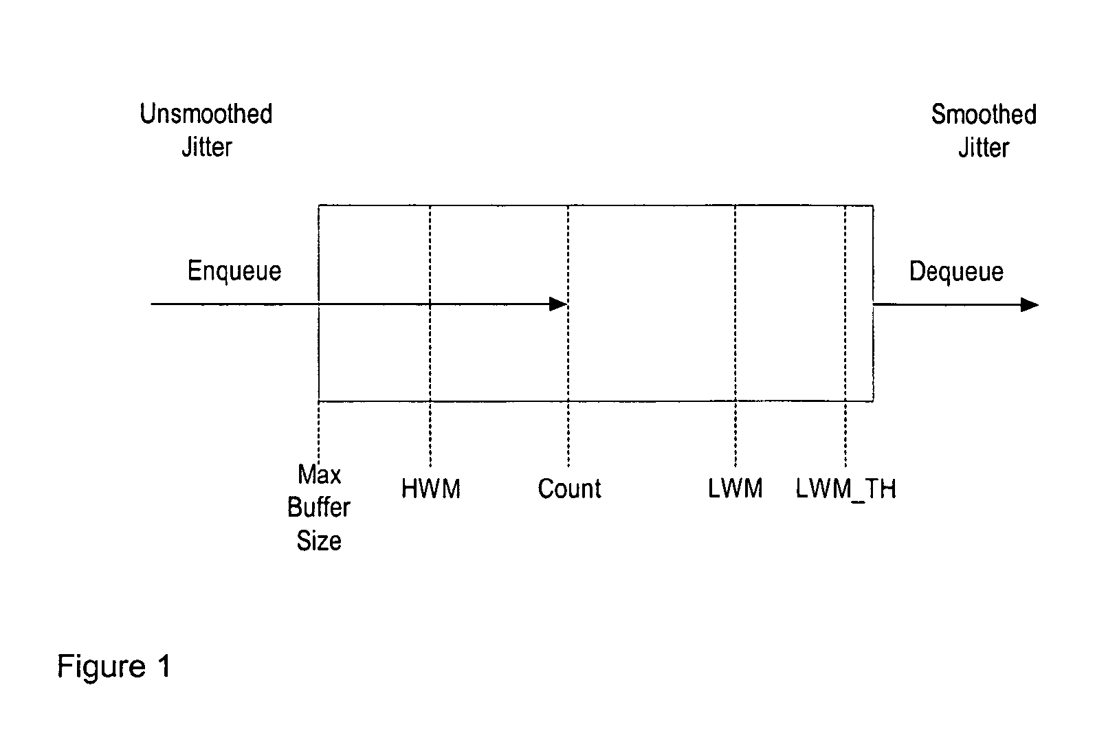
[0011]FIG. 1 shows an adaptive jitter buffer according to the present invention, for enqueueing data packets that have been subjected to unsmoothed jitter and dequeueing the data at a steady rate so that the dequeued data is subjected to smoothed jitter. The total number of packets capable of being stored in the buffer is represented by the maximum buffer size, while the minimum number of packets is LWM_TH. The “count” gives the number of packets in the buffer at any time, while the low water mark (LWM) indicates how far the buffer is away from underflow, and the high water mark (HWM) tracks the delay within the buffer.
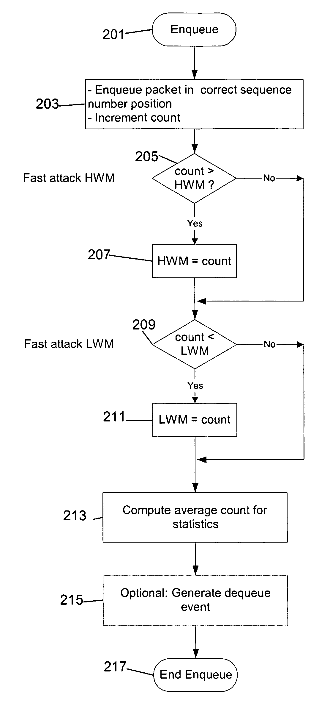
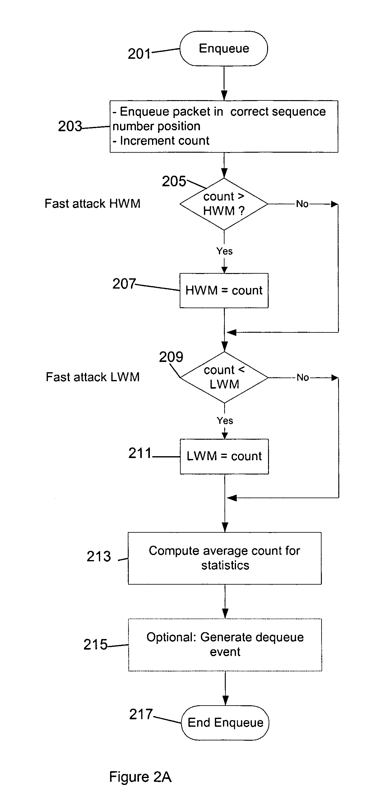
[0012]Turning to FIG. 2, upon receipt of a data packet an Enqueue event is initiated (step 201 of FIG. 2A). The received packet is loaded into the buffer in correct sequence number position, and “count” is incremented to reflect the current number of packets (step 203).
[0013]If count exceeds HWM then HWM is set to count (step 205). If the count does not exceed HWM, or...
PUM
 Abstract
Description
Claims
Application Information