Quick change barrel system for a firearm

a barrel system and firearm technology, applied in the field of firearms, can solve the problems of critical weapon failure, various malfunctions, and large heat generated by weapons, and achieve the effects of convenient use, improved efficiency, and rapid deploymen

Active Publication Date: 2009-08-18
MAGPUL INDUSTRIES
View PDF13 Cites 61 Cited by
  • Summary
  • Abstract
  • Description
  • Claims
  • Application Information

AI Technical Summary

Benefits of technology

[0008]In view of the foregoing disadvantages inherent in the known types of barrel systems, this invention provides an improved quick change barrel system with increased utility, intuitive use and rapid deployment. As such, the present invention's general purpose is to provide a new and improved quick change barrel system that is more efficient to operate and maintain, and presents an intuitive interface for users.
[0009]To accomplish these objectives, the quick change barrel system comprises a barrel which is mounted in a cantilevered manner. The rear of the barrel slides and mounts into a barrel trunnion and is subsequently locked into place with a barrel lock ring via an interrupted, non-continuous thread that mates with the barrel trunnion. A folding wire handle is provided to assist in applying leverage to turn the barrel lock ring thereby applying pressure to the barrel extension flange and providing a sealed joint. A spring-loaded detent (barrel lock plunger) locks into grooves on the barrel lock ring to prevent it from working loose.

Problems solved by technology

Due to the quantity and rate of fire, these weapons generate a significant amount of heat, primarily in the barrel and gas operating system (if one is present).
This may cause various malfunctions including critical weapon failure (feeding & extraction failures, blown barrels, bolt failure etc.).
However, these systems can have various drawbacks including low effectiveness, weight, bulk, complexity and cost.
Rifles are not expected to generate the heat levels seen on machine-guns.
Barrels were never intended to be readily removed especially at the operator level.
While this approach has worked historically, this type of design has imposed a number of limitations on these systems.
With increased detachable box magazine capacity, lighter ammunition and the demands of high-end users such as special forces operators, rifles are experiencing heat issues similar to machine-guns.

Method used


Image

  • Quick change barrel system for a firearm
  • Quick change barrel system for a firearm
  • Quick change barrel system for a firearm

Examples


Embodiment Construction

[0029]With reference now to the drawings, the preferred embodiment of the firearm is herein described. It should be noted that the articles “a”, “an” and “the”, as used in this specification, include plural referents unless the content clearly dictates otherwise.

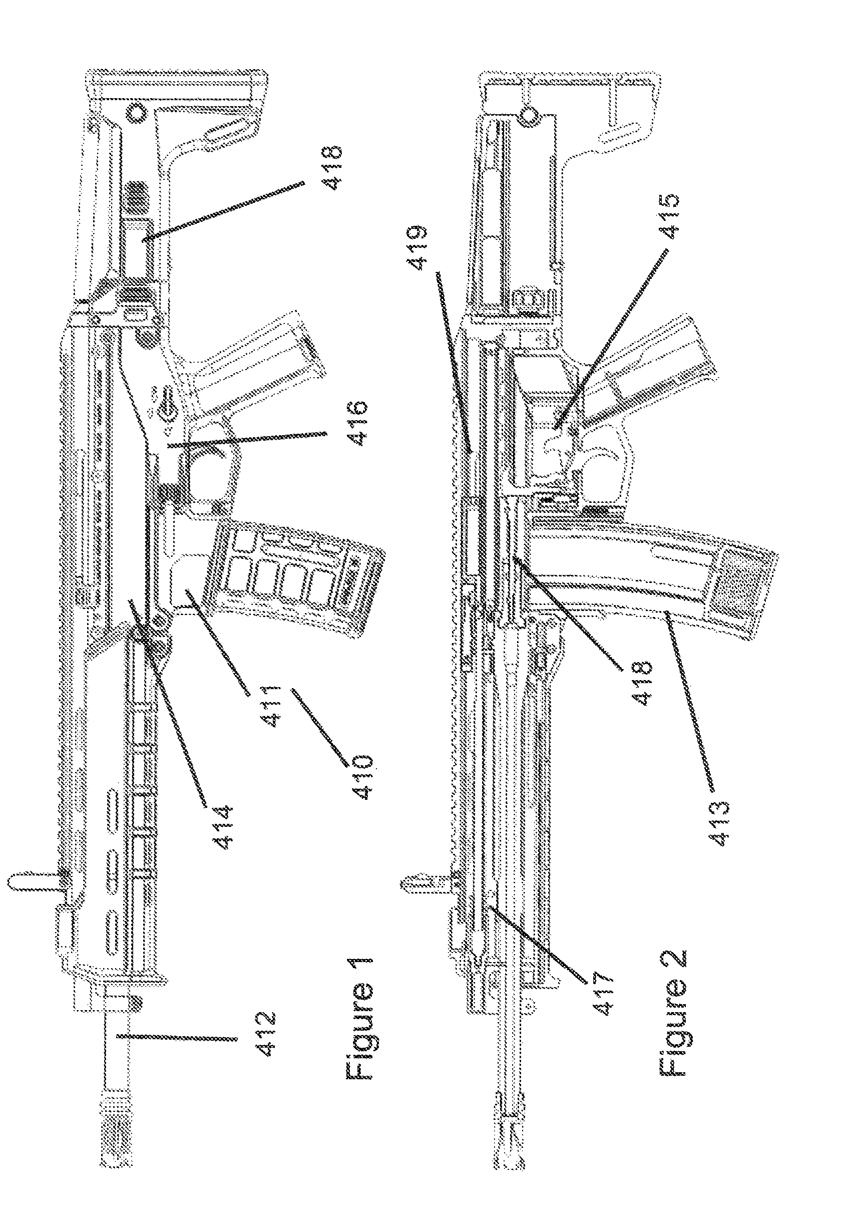
[0030]With reference to FIG. 1, the firearm 10, as disclosed in the parent provisional application, has four major components, namely the barrel 412, receiver 414, grip housing 416 and stock 418. Internal parts are generally located in the receiver 414 and grip housing 416. FIG. 2 depicts a trigger control group 415 and a magazine 413 as residing in the grip housing 416 and a short stroke gas piston system 417 and charging system 419 in the receiver 414. The firing pin 418 is also located in the receiver 414.

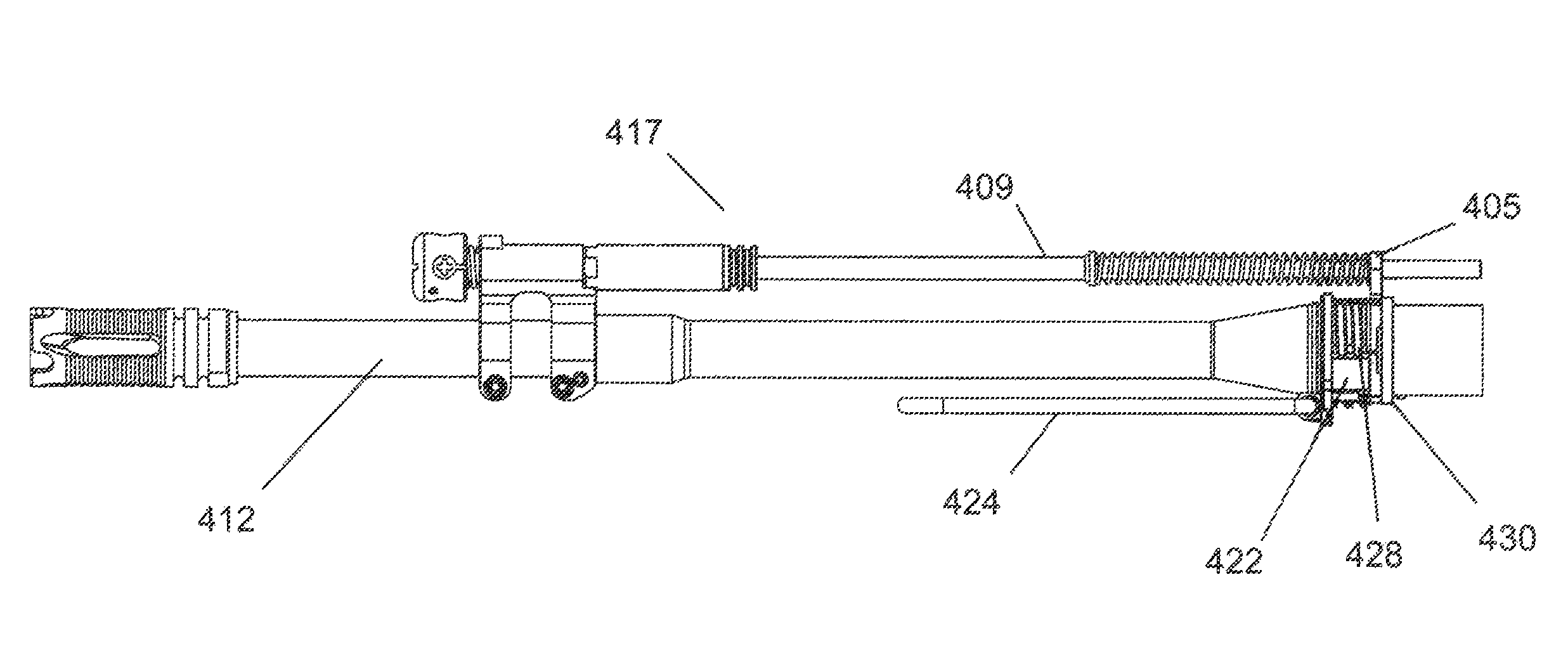
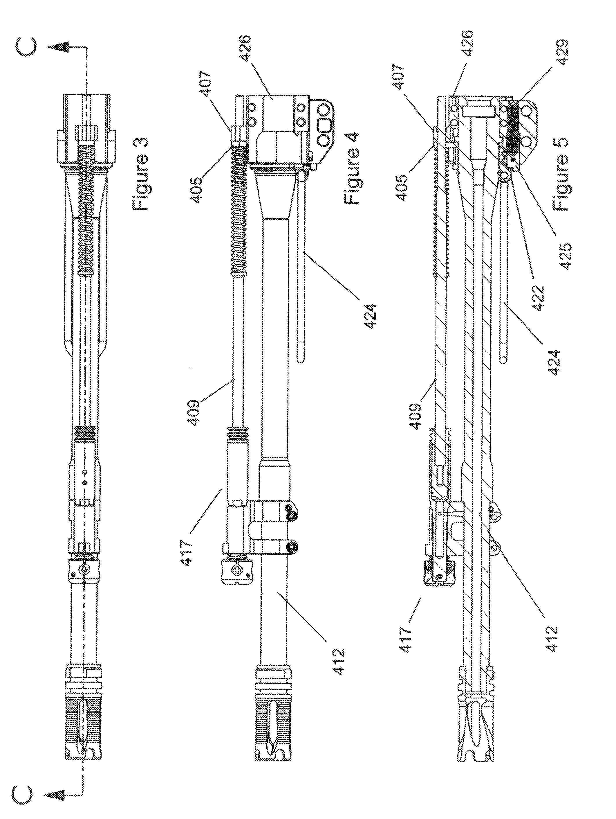
[0031]The firearm 410 has a free floating barrel 412 which is cantileverally attached to receiver 414 (FIG. 2). The barrel assembly itself is depicted in FIGS. 3-5. In these depictions, a stripped M-16 / AR15 barrel is use...


PUM


Abstract

The present invention is an improved quick change barrel system for a firearm. It features an interlocking trunnion and lock ring that hold the barrel in place proximate the receiver. Intermittent threading provides multiple points of interface. A foldable handle is provided to allow safe removal of the lock ring and additional torque for attachment and removal of the lock ring from the system.

Description

CROSS-REFERENCES TO RELATED APPLICATIONS[0001]This Application claims priority as a non-provisional perfection of prior filed U.S. Provisional Application 60 / 884,615, filed on Jan. 11, 2007 and incorporates the same by reference in its entirety.FIELD OF THE INVENTION[0002]The present invention relates to the field of firearms and more particularly relates to a new rifle platform with enhanced utility innovative components and increased modularity.BACKGROUND OF THE INVENTION[0003]Prior firearms have been, as a whole, adequate for their purposes. However, the advent of improved technologies in other fields, combined with the demands of current military tactics, both offensive and defensive, have created a need for a firearm that improves upon the current designs in the art. Practically speaking, the need has arisen for a lighter and more efficient weapon; one that is easily maintained, simple to operate and assemble, and easily enhanced as need requires.[0004]Of particular need is a q...

Claims


Application Information

Patent Timeline
Patent Type & Authority Patents(United States)
IPC IPC(8): F41A21/00
CPCF41A21/481
Inventor NAKAYAMA, BRIAN
Owner MAGPUL INDUSTRIES
Why Eureka
Try Eureka