Portable telescoping tower assembly

Inactive Publication Date: 2009-08-18
LIEBERMAN PHILLIP L +1
View PDF31 Cites 54 Cited by
  • Summary
  • Abstract
  • Description
  • Claims
  • Application Information

AI Technical Summary

Benefits of technology

[0026]Each of the successive sections are progressively small

Problems solved by technology

The portable towers are often deployed in adverse conditions, such as desert or swamp locations, which are difficult on moving components.
The bearings may provide ex

Method used


Image

  • Portable telescoping tower assembly
  • Portable telescoping tower assembly
  • Portable telescoping tower assembly

Examples


Embodiment Construction

[0035]The embodiments discussed herein are merely illustrative of specific manners in which to make and use the invention and are not to be interpreted as limiting the scope of the instant invention.

[0036]While the invention has been described with a certain degree of particularity, it is to be noted that many modifications may be made in the details of the invention's construction and the arrangement of its components without departing from the spirit and scope of this disclosure. It is understood that the invention is not limited to the embodiments set forth herein for purposes of exemplification.

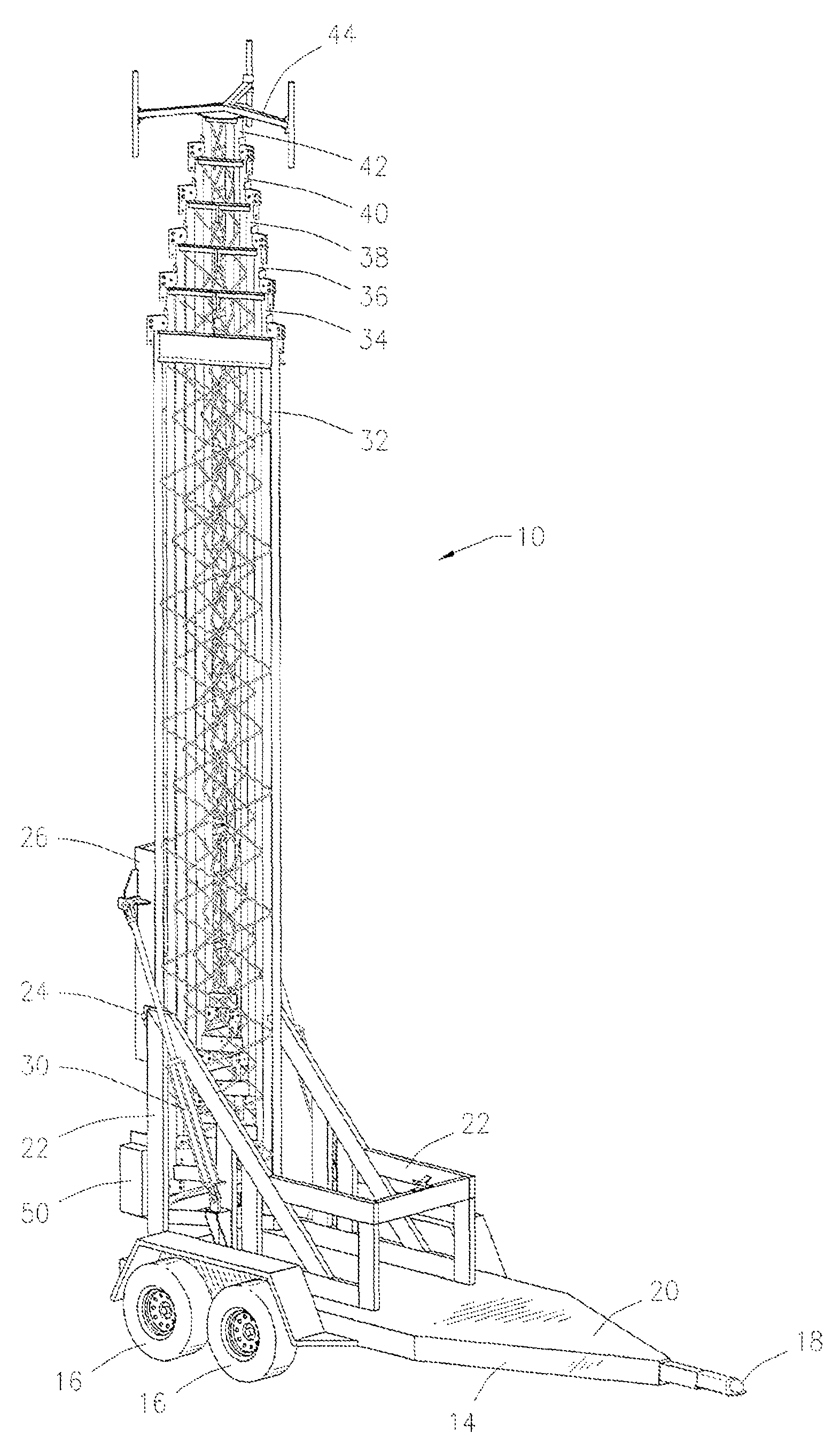
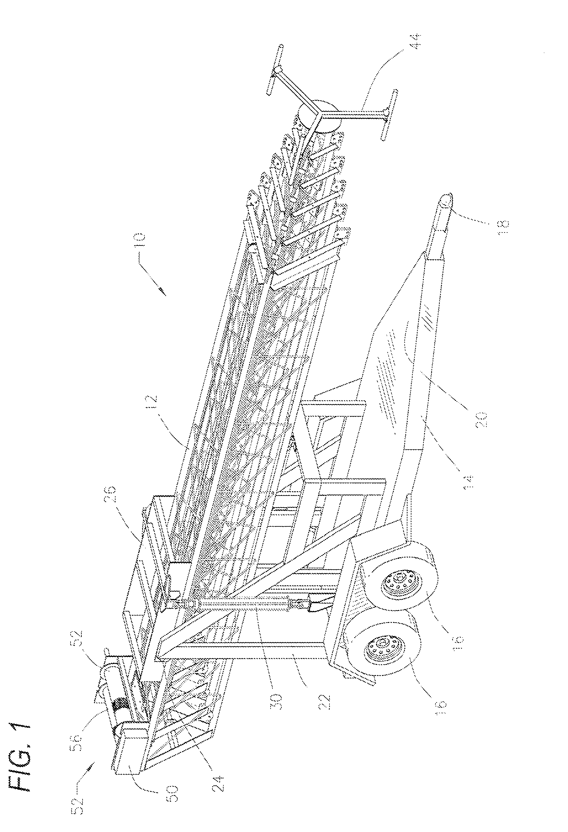
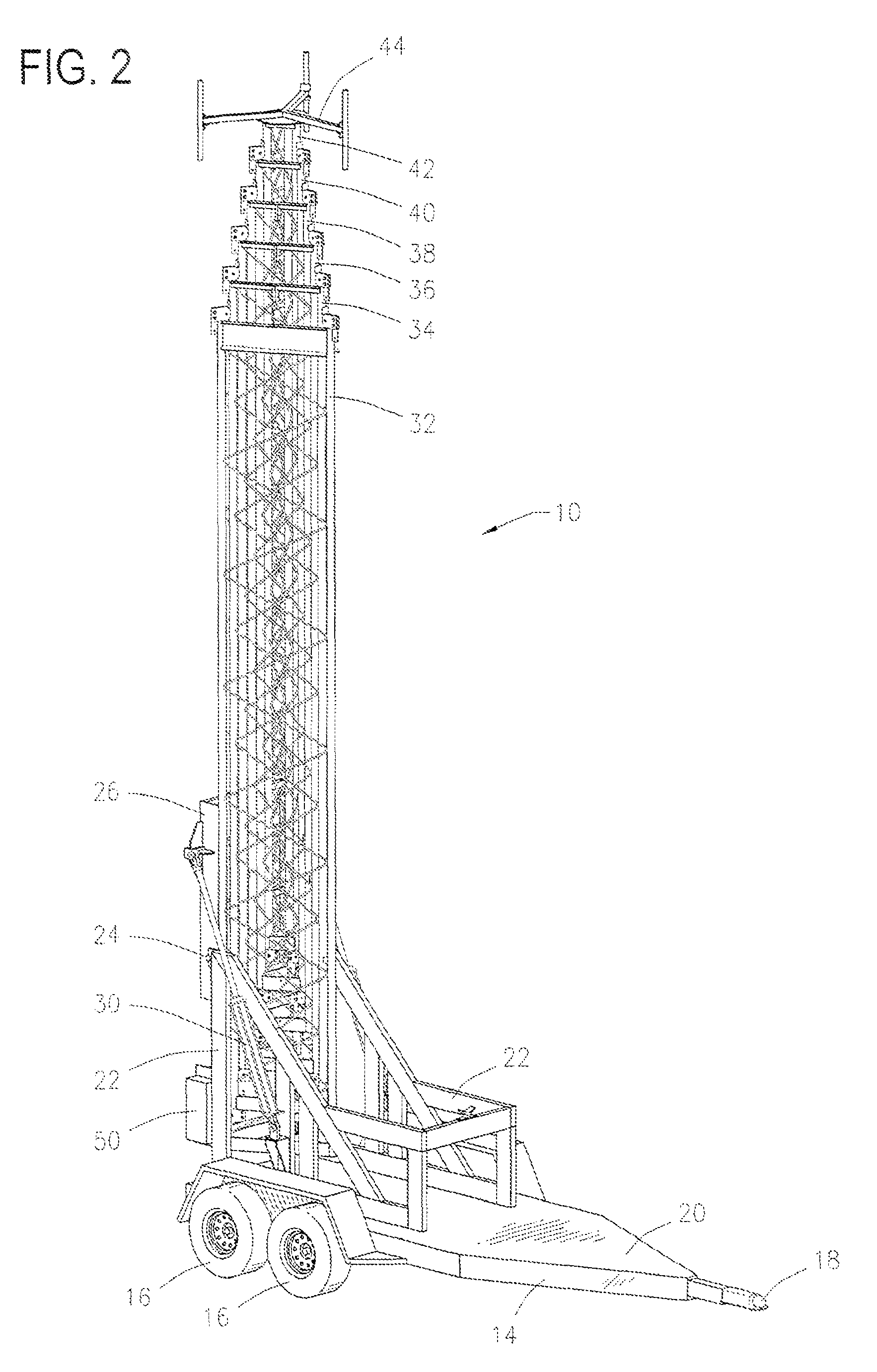
[0037]Referring to the drawings in detail, FIG. 1 illustrates a perspective view of a portable telescoping tower assembly 10 constructed in accordance with the present invention which is in the horizontal, storage and transportation position.

[0038]The assembly 10 includes a tower 12 which will be described in detail below. The tower 12 is mounted on a vehicle, such as a truck, or on a tra...


PUM


Abstract

A portable telescoping tower assembly. The assembly includes a tower mounted on a trailer wherein the tower includes a plurality of telescoping sections that extend for use and retract and nest for storage and transportation. At least one cylindrical ram moves the tower between horizontal and vertical positions. A motor extends and retracts the plurality of sections. Each of the sections includes a plurality of external edges with each of the external edges including at least one protruding guide to mate with and receive an adjoining section.

Description

BACKGROUND OF THE INVENTION[0001]1. Field of the Invention[0002]The present invention is directed to a portable, telescoping tower assembly that may be mounted on a standard trailer, vehicle, skid, or barge for rapid deployment to support equipment at desired heights. In particular, the present invention is directed to a portable, telescoping tower assembly including a series of telescoping sections that extend for use and retract and nest together for storage and transportation.[0003]2. Prior Art[0004]Portable tower assemblies are known and are often used to support equipment at desired heights when rapid deployment is warranted or when circumstances are of a temporary nature which do not justify permanent installation. For example, cellular telecommunications services may be desirable at a sports facility or in disaster situations. Additionally, support of lighting equipment at sporting events may be desirable. Portable towers are also used in military operations for telecommunica...

Claims


Application Information

Patent Timeline
IPC IPC(8): E04H12/34B66C23/06E04H12/18
CPCE04H12/10E04H12/187E04H12/182
Inventor LIEBERMAN, PHILLIP L.
Owner LIEBERMAN PHILLIP L
Why Eureka
Try Eureka