Lamp

a technology for lamps and heat sinks, applied in the field of lamps, can solve the problems of low heat dissipation efficiency of heat sinks, and achieve the effect of improving heat dissipation efficiency

Inactive Publication Date: 2009-08-18
SUNONWEALTH ELECTRIC MACHINE IND
View PDF10 Cites 94 Cited by
  • Summary
  • Abstract
  • Description
  • Claims
  • Application Information

AI Technical Summary

Benefits of technology

[0006]It is therefore the primary objective of this invention to provide a lamp that overcomes the problems of the prior art described above to enhance heat dissipating efficiency.

Problems solved by technology

Unfortunately, the air flows “a” may block the air flows “A” with the heat from flowing to the outer spaces of the housing 91 through the outlet section 914 and may cause turbulence near the inlet section 913, and these lower heat dissipating efficiency of the heat sink 93 and the fan 94.

Method used


Image

  • Lamp
  • Lamp
  • Lamp

Examples


first embodiment

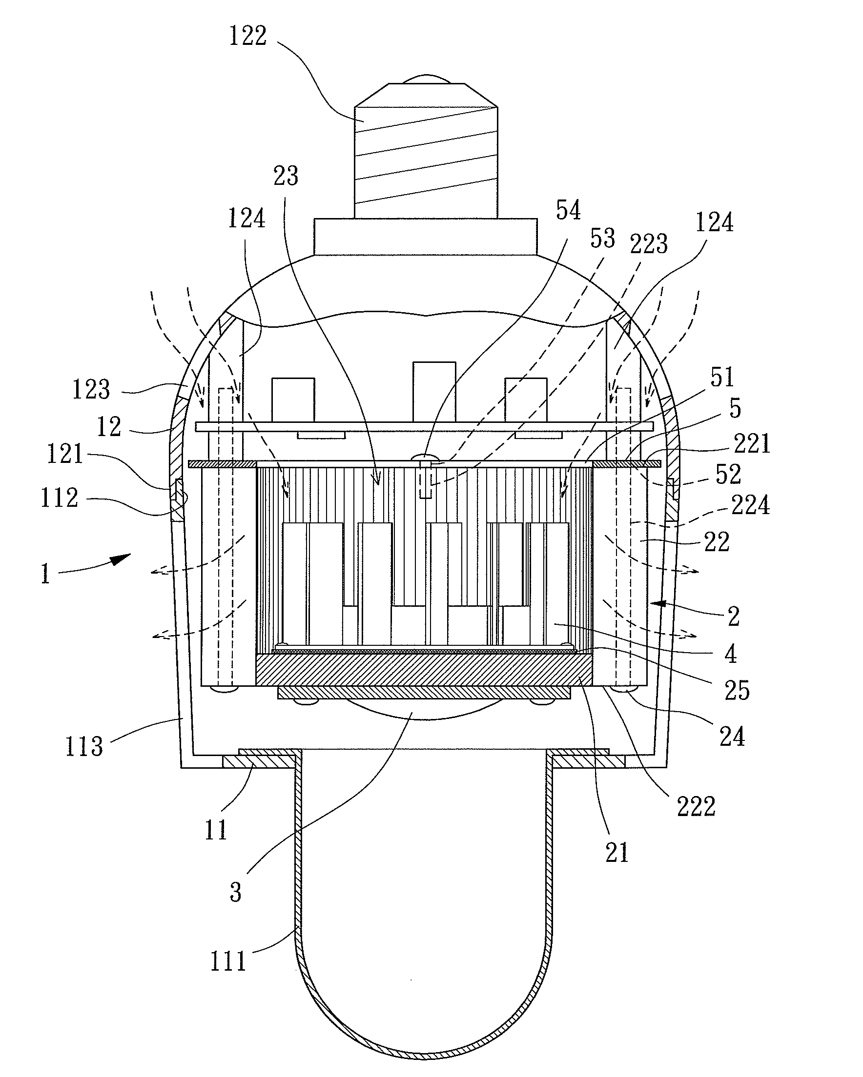
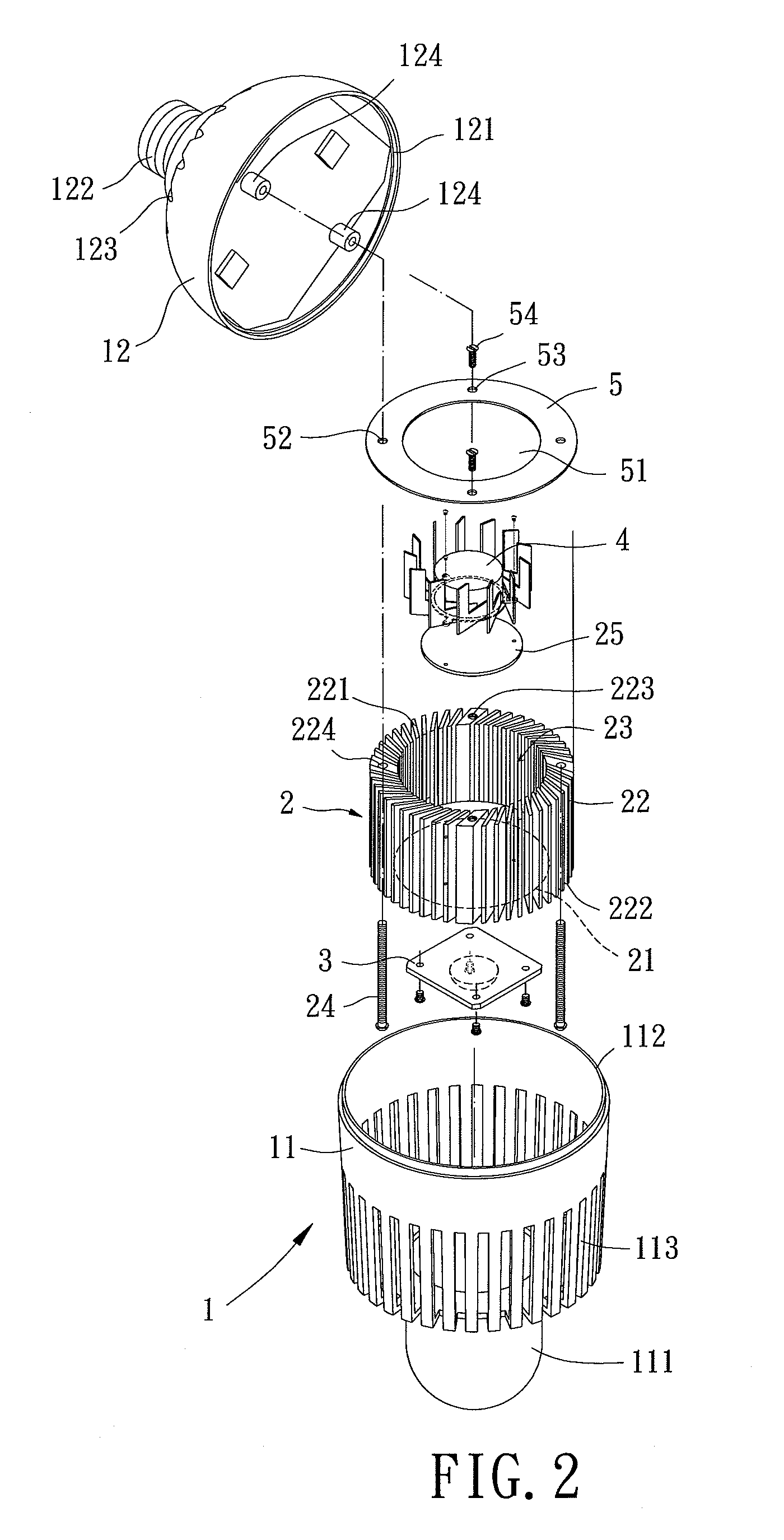
[0023]The housing 1 is preferred an integrally made hollow housing or a housing consisting of a plurality of pieces, which is provided for receiving some related components. In the first embodiment, the housing 1 includes a first shell 11 and a second shell 12. The first shell 11 has a lens 111 at one end thereof while the other end of the first shell 11 forms a first engaging portion 112. An outlet section 113 is formed on the wall of the first shell 11, preferably between the lens 111 and the first engaging portion 112 and in a shape of plural slots. One end of the second shell 12 forms a second engaging portion 121 for engaging with the first engaging portion 112 to form the whole housing 1 while the other end of the second shell 12 has a base 122. An inlet section 123 is formed on the wall of the second shell 12, preferably between the base 122 and the second engaging portion 121 and also in a shape of plural slots. Furthermore, a plurality of positioning protrusions 124 are for...

second embodiment

[0030]FIGS. 4 and 5 show a lamp of a second embodiment according to the preferred teachings of the present invention modified from the first embodiment, which includes a housing 1, a heat sink 2, a light emitting member 3, a fan 4 and a blocking ring 6, wherein the heat sink 2 is without the positioning holes 223. The blocking ring 6 also is mounted inside the housing 1 and between the inlet section 123 and the heat sink 2 and has an inlet hole 61 aligned with the chamber 23 of the heat sink 2. The blocking ring 6 has a plurality of through holes 62 around the inlet hole 61, for the fixing members 24 to extend through. Preferably, the inlet hole 61 extends axially along a central line of the blocking ring 6. Besides, for the convenience of combination between the blocking ring 6 and the heat sink 2, the outer edge of the blocking ring 6 forms a flange 63 extending in a direction from the first ends 221 to the second ends 222 of the fins 22 to fit on the outer lateral wall of the fin...


PUM


Abstract

A lamp comprises a housing, a heat sink, a light emitting member, a fan and a blocking ring. The housing includes an outlet section and an inlet section formed on the wall thereof. The heat sink is mounted inside the housing and includes a base plate and a plurality of fins, with the fins being close to the outlet section of the housing and arranged around the base plate to form a chamber. Each of the fins has a first end facing the inlet section of the housing and a second end connecting with the base plate. The light emitting member is fixed to the base plate of the heat sink. The fan is fixed inside the chamber of the heat sink. The blocking ring is mounted inside the housing and between the inlet section and the heat sink and includes an inlet hole aligned with the chamber of the heat sink. By the blocking ring, parts of the heated air flows are blocked from flowing back to the inlet section to avoid turbulence resulting from flowing back air flows. Consequently, the air flows risen by the fan and receiving the heat inside the housing can flow smoothly to out of the housing through the outlet section to enhance heat dissipating efficiency of the heat sink and the fan.

Description

BACKGROUND OF THE INVENTION[0001]1. Field of the Invention[0002]The present invention relates to a lamp, more particularly, to a lamp that can automatically dissipate heat generated by the lamp itself.[0003]2. Description of the Related Art[0004]Referring to FIG. 1, a conventional lamp 9 that can dissipate heat generated by the lamp 9 itself includes a housing 91 forming a lens 911 and a base 912 on two ends thereof respectively, a light emitting member 92, a heat sink 93 and a fan 94. The housing 91 has an inlet section 913 and an outlet section 914 on the wall thereof between the lens 911 and the base 912. The light emitting member 92, the heat sink 93 and the fan 94 are inside the housing 91, with two ends of the heat sink 93 respectively connecting with the housing 91 and the light emitting member 92. Besides, an outer surface of the heat sink 93 forms a plurality of fins 931 jointly surrounding a chamber 932 that receives the fan 94.[0005]In use, the lamp 9 is generally coupled...

Claims


Application Information

Patent Timeline
Patent Type & Authority Patents(United States)
IPC IPC(8): F21V29/00
CPCF21V29/02F21K9/135F21V29/83F21V29/677F21V29/773F21V29/507F21Y2101/02F21K9/232F21Y2115/10F21V29/67F21V29/74
Inventor HORNG, ALEXZHONG, ZHI-HAOHU, HENG-YU
Owner SUNONWEALTH ELECTRIC MACHINE IND
Why Eureka
Try Eureka