Connector for electrical and optical cables

a technology of electrical and optical cables, applied in the direction of optical elements, coupling device connections, instruments, etc., can solve the problems of increasing time expenditure, requiring appreciable time expenditure, and causing a lot of connection labor, and achieve the effect of convenient turning

Inactive Publication Date: 2009-08-18
WEIDMULLER INTERFACE GMBH & CO KG
View PDF14 Cites 16 Cited by
  • Summary
  • Abstract
  • Description
  • Claims
  • Application Information

AI Technical Summary

Benefits of technology

[0010]Accordingly, it is a primary object of the present invention to provide on a plug and socket connector arrangement a pair of colinearly-arranged inner and outer locking sleeves having adjacent ends that are externally and internally threaded, respectively, which adjacent ends contain a plurality of longitudinal slits that define a plurality of circumferentially spaced resilient sectors, respectively, the resilient sectors being radially expanded and radially contracted, respectively, as the locking sleeves are axially displaced together, thereby to produce engagement between the screw threads, whereby upon slight relative rotation of the locking sleeves, the locking sleeves and the plug and socket connectors are locked together.
[0014]Both plug and socket connector parts in each case are provided with sleeves that preferably have radially elastic ring segments; therefore, one can achieve a particularly easily handled and workable plug-in connection, which also will be compatible with the plug and socket parts especially according to the M standard without sleeves that feature such a subdivision of the screw threads into ring segments. This, moreover, also provides compatibility with relatively many known “fast connection systems,” which have until now been developed for the “M standard.”
[0016]The following special advantage must be emphasized: The full compatibility with plug and socket parts of known design is preserved, that is to say, the plug part and also the socket part are likewise compatible with conventional plug parts and socket parts of the corresponding M standard that depends on the dimensions (for example, M8 or M12). Here again, one can provide for a fast connection without screws in that the sleeve is first pushed back and that the internal bodies are then stuck into each other, whereupon by axially moving the sleeve, the sleeves are locked as they run up on the widening or tapering section. The sleeves are then easily turned.

Problems solved by technology

This requires an appreciable time expenditure, especially when making a plurality of such plug-in connections.
On the electrical connectors commonly used in the automation technology, the connections for this purpose are often arranged relatively close to each other, which likewise increases the time expenditure and makes connection rather laborious.
This is disadvantageous in that the past designs necessitate a rather expensive production and processing both of the sleeve of the plug part and the processing of the socket inasmuch as the currently known designs are based on the idea that they contain either bayonet-like connection possibilities or that both the sleeve of the plug part and the socket must be provided with thread-free areas running along the axial direction, which then facilitate an axial combination or connection without the need for a rotation and which permit an axial securing only at the last moment by means of a rotation.
In the latter variant, a connection is made to an inside screw thread that is not provided with the axially free areas and, furthermore, in that way, one cannot achieve any time gain when compared to known screw operations.

Method used


Image

  • Connector for electrical and optical cables
  • Connector for electrical and optical cables
  • Connector for electrical and optical cables

Examples


Embodiment Construction

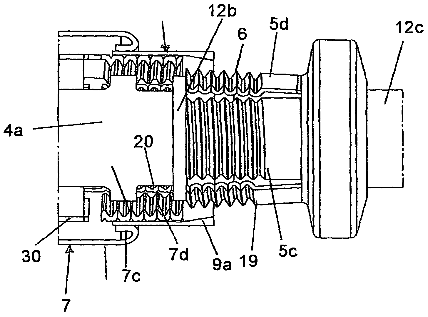
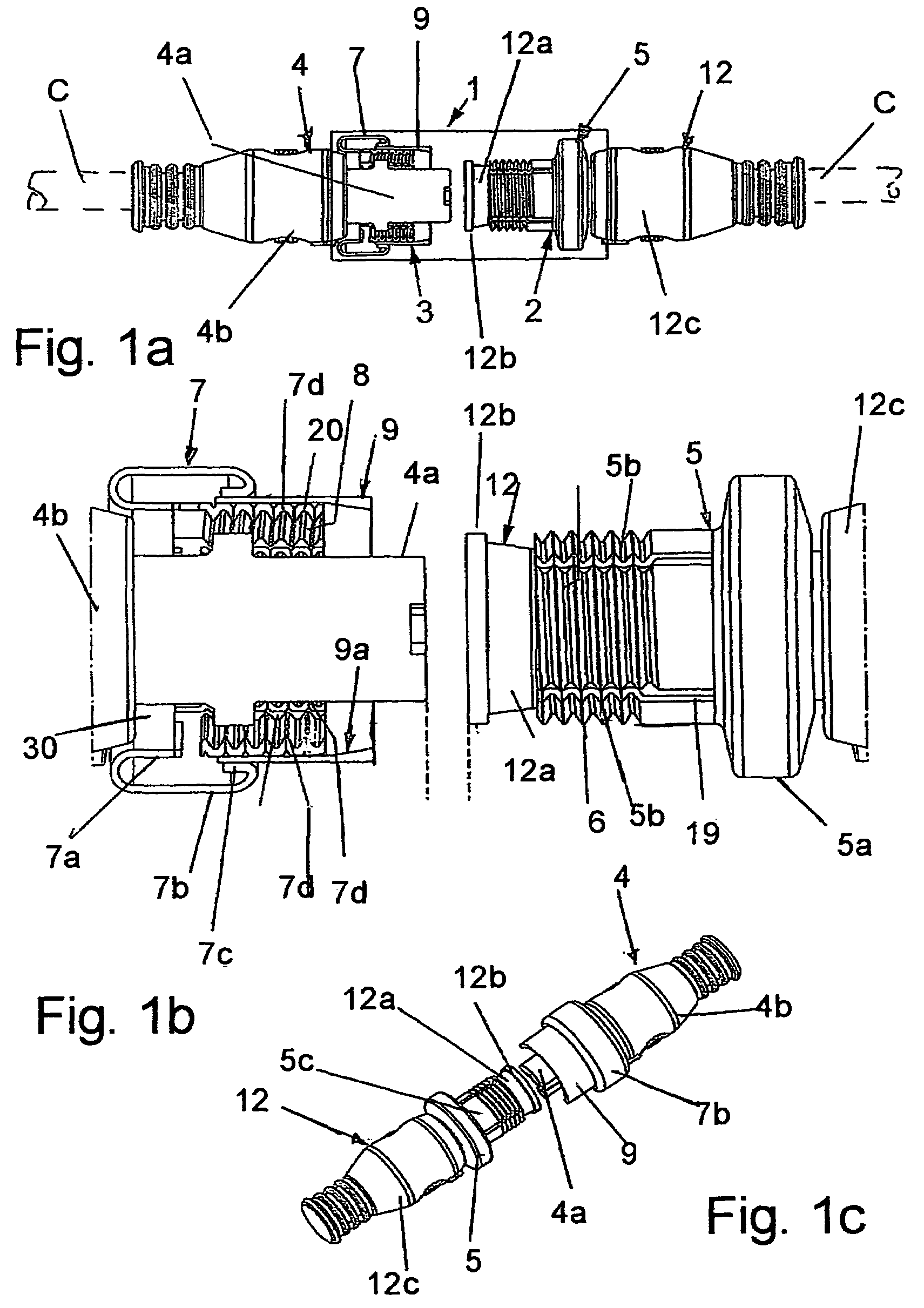
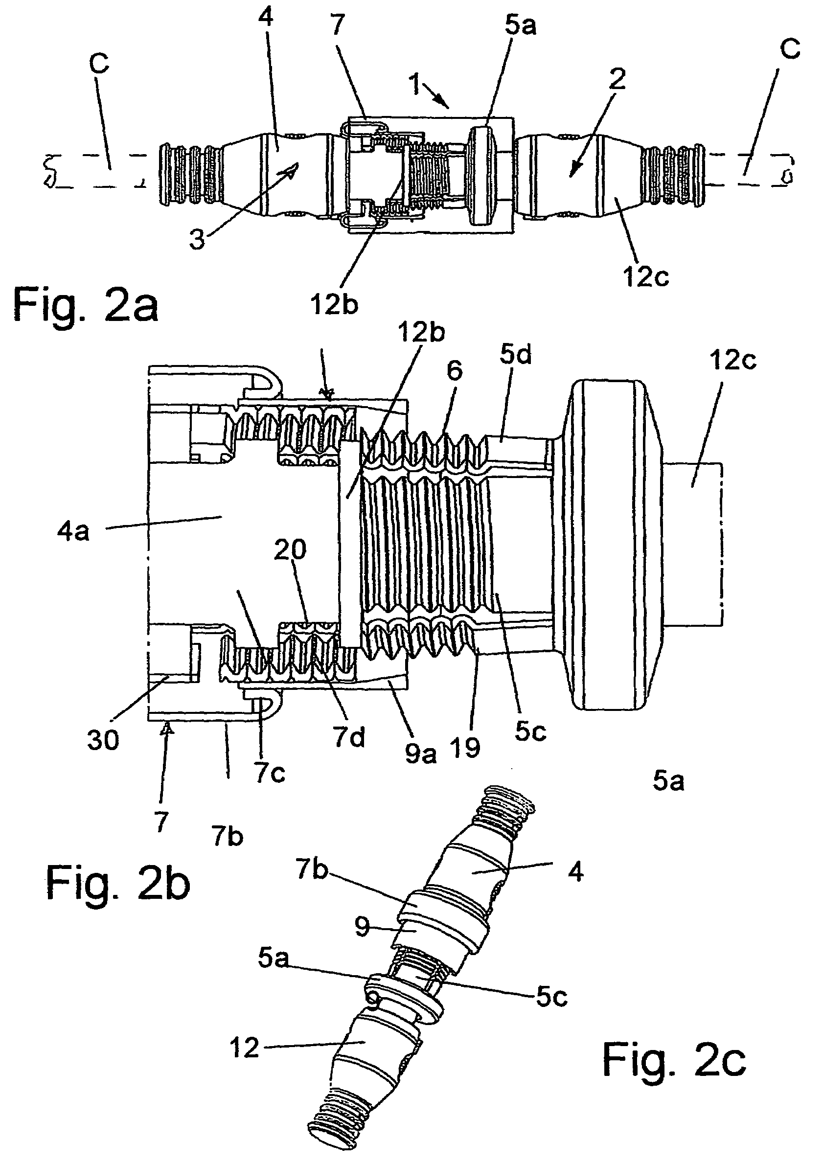
[0024]Referring first more particularly to FIGS. 1a-1c, the connector apparatus for connecting together a pair of electrical or fiber optic cables C and C′ include colinearly-arranged plug and socket connectors 2 and 3 having a plurality of corresponding male and female contacts, respectively (not shown). The plug connector includes a plug body 12 formed from an electrically insulating synthetic plastic material and including a free first end portion 12a that is conical and diverges outwardly in the direction of the socket and which terminated in an annular stop flange 12b. The socket body 4 is similarly formed from a synthetic plastic insulating material and includes an integral first end portion 4a adjacent the plug body first end portion.

[0025]Mounted for axial and rotational displacement on the plug first end portion is a tubular inner locking sleeve member 5 having a first end portion carrying a plurality of external screw threads 6, and a second end portion including an enlarg...


PUM


Abstract

A plug and socket connector arrangement for electrical or fiber optic cables includes a pair of tubular locking sleeves mounted for axial and rotational displacement on the plug and connector bodies, which locking sleeves have adjacent ends provided with internal and external screw threads, respectively. The adjacent sleeve ends each contain a plurality of circumferentially spaced longitudinal slits that define a plurality of resilient threaded sectors. After the plug and socket connectors are brought into connected engagement, the locking sleeves are successively displaced from retracted separated positions axially together toward an adjacent locked position, whereby the resilient inner sleeve sectors are initially radially expanded, and the resilient outer sleeve sectors are subsequently radially contracted. The inner and outer screw threads are thus brought into threaded engagement, whereupon the locking sleeves are slightly relatively rotated to lock the sleeves together.

Description

BACKGROUND OF THE INVENTION[0001]1. Field of the Invention[0002]A plug and socket connector arrangement includes a pair of tubular locking sleeves mounted for axial and rotational displacement on the plug and socket connector bodies, which locking sleeves have adjacent ends provided with internal and external screw threads, respectively, which adjacent ends contain a plurality of longitudinal slits that define a plurality of circumferentially spaced resilient threaded sectors. After the plug and socket connectors are brought into connected engagement, the locking sleeves are successively displaced from retracted separated positions axially together toward an adjacent locked position, whereby the resilient inner sleeve sectors are initially radially expanded, and the resilient outer sleeve sectors are subsequently radially contracted, thereby bringing the inner and outer screw threads into threaded engagement, following which the locking sleeves are slightly relatively rotated to loc...

Claims


Application Information

Patent Timeline
Patent Type & Authority Patents(United States)
IPC IPC(8): H01R13/62H01R24/58
CPCH01R13/622G02B6/3893G02B6/3894
Inventor NICKOL, MARCELL
Owner WEIDMULLER INTERFACE GMBH & CO KG
Why Eureka
Try Eureka