Unlock instant, AI-driven research and patent intelligence for your innovation.

Perpendicular magnetic recording head utilizing tensile stress to optimize magnetic pole layer domain structure

a magnetic recording head and perpendicular magnetic technology, applied in the field of thin film magnetic heads, can solve the problems of unintentional erasure of information recorded on a recording medium, and insufficient knowledge regarding the relationship between, so as to suppress unintentional erasure of information

Active Publication Date: 2009-08-18
SAE MAGNETICS (HK) LTD
View PDF21 Cites 3 Cited by
  • Summary
  • Abstract
  • Description
  • Claims
  • Application Information

AI Technical Summary

Benefits of technology

The present invention provides a thin film magnetic head and a magnetic recording apparatus that can prevent unintended erasure of information at non-recording times. The invention optimizes the magnetic domain structure of the magnetic pole layer by using a nonmagnetic layer that buries the magnetic pole layer and has a tensile stress in at least part of it. This helps to prevent leakage of magnetic flux and minimize the influence of the magnetoelastic effect. The thin film magnetic head includes a thin film coil for generating a magnetic flux, a magnetic pole layer extending rearward from the recording-medium-facing surface and emitting the magnetic flux generated by the thin film coil, and a nonmagnetic layer which buries the magnetic pole layer and has a tensile stress in at least part of it. The magnetic recording apparatus includes the thin film magnetic head and a recording medium. The technical effect of the invention is to optimize the magnetic domain structure of the magnetic pole layer and prevent unintended erasure of information at non-recording times.

Problems solved by technology

The “unintended erasure of information at the non-recording time” is a trouble in the recording characteristic such that information recorded on a recording medium is erased unintentionally by leakage of a magnetic flux (remanent magnetization) remaining in the magnetic pole layer due to the magnetic domain structure of the magnetic pole layer as a part for emitting a magnetic flux for recording at the non-recording time, that is, in a state where the thin film coil is not energized (no magnetic flux for recording is generated).
Although it is known that the composition of the magnetic material and magnetostriction of a magnetic component exert an influence on the magnetic domain structure of the magnetic pole layer, sufficient knowledge regarding the relation between an unintended information erasure occurrence mechanism at the time of non-recording time and the magnetic domain structure of the magnetic pole layer is not obtained conventionally.
It is consequently an issue how to set the magnetic domain structure of the magnetic pole layer in order to suppress unintended erasure of information at the non-recording time.

Method used


Image

  • Perpendicular magnetic recording head utilizing tensile stress to optimize magnetic pole layer domain structure
  • Perpendicular magnetic recording head utilizing tensile stress to optimize magnetic pole layer domain structure
  • Perpendicular magnetic recording head utilizing tensile stress to optimize magnetic pole layer domain structure

Examples


Embodiment Construction

[0036]Embodiments of the invention will now be described in detail hereinbelow with reference to the drawings.

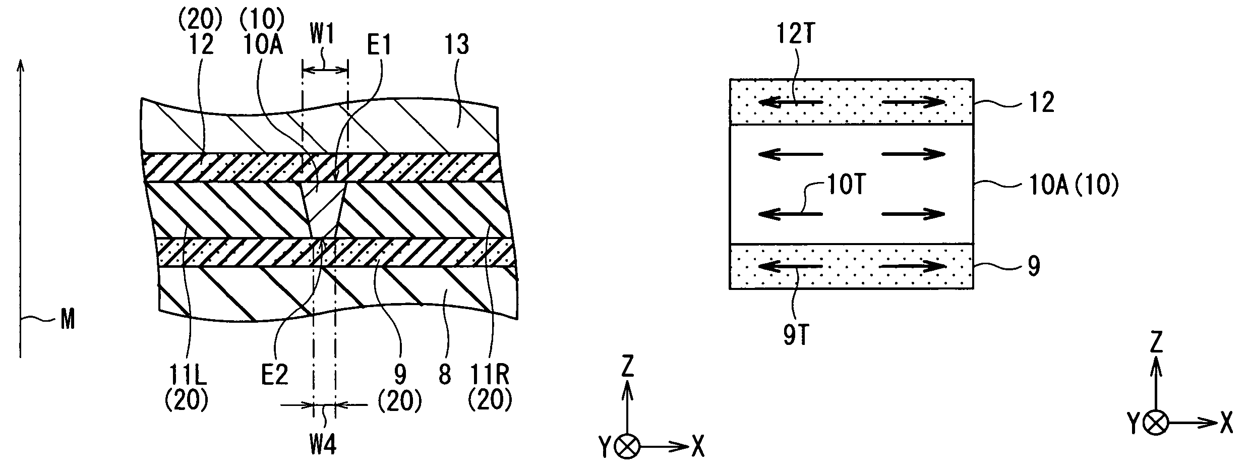
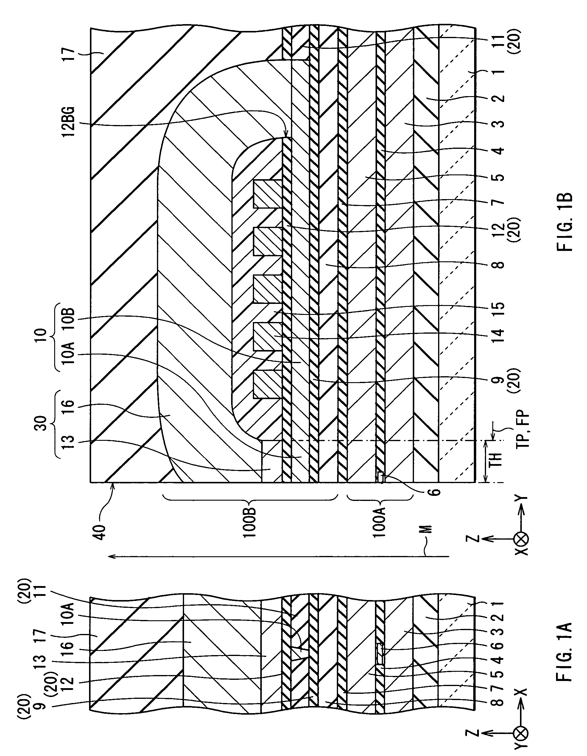
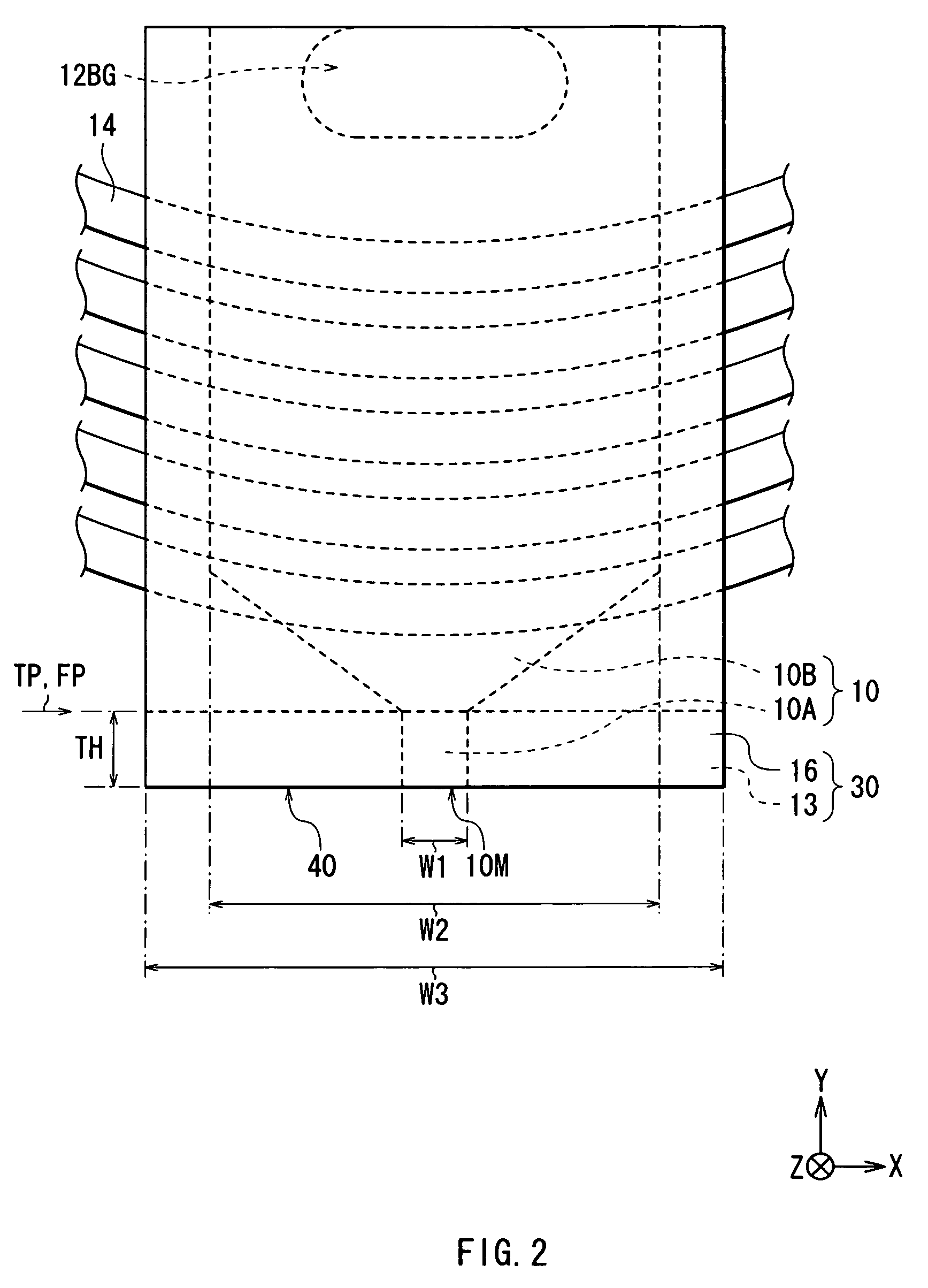
[0037]First, the configuration of a thin film magnetic head according to an embodiment of the invention will be described with reference to FIGS. 1A and 1B and FIG. 2. FIGS. 1A and 1B show sectional configurations of a thin film magnetic head. FIG. 1A shows a sectional configuration parallel to an air bearing surface (a sectional configuration along an XZ plane) and FIG. 1B shows a section configuration perpendicular to the air bearing surface (a sectional configuration along a YZ plane). FIG. 2 is a plan view showing the configuration (plane configuration seen from the Z-axis direction) of the thin film magnetic head illustrated in FIGS. 1A and 1B. An upward arrow M shown in FIGS. 1A and 1B indicates the travel direction of a recording medium (not shown) relative to the thin film magnetic head (medium travel direction M).

[0038]In the following description, the distance in t...


PUM

PropertyMeasurementUnit
thicknessaaaaaaaaaa
thicknessaaaaaaaaaa
thicknessaaaaaaaaaa

Abstract

A thin film magnetic head is constructed so that in the case where a magnetic pole layer has a tensile stress, an insulating layer under the magnetic pole layer has a tensile stress and a gap layer on the magnetic pole layer similarly has a tensile stress. The tensile stress in the magnetic pole layer is maintained by the mechanical influence of the tensile stresses in the insulating layer and the gap layer. Consequently, the magnetic domain structure of the magnetic pole layer is optimized so as to suppress leakage of a magnetic flux remained in the magnetic pole layer to the outside at the non-recording time due to the influence of a magnetoelastic effect immediately after recording. Thus, unintended erasure of information recorded on a recording medium is suppressed.

Description

BACKGROUND OF THE INVENTION[0001]1. Field of the Invention[0002]The present invention relates to a thin film magnetic head having at least an inductive magnetic transducer for recording, a method of manufacturing the same, and a magnetic recording apparatus in which a thin film magnetic head is mounted.[0003]2. Description of the Related Art[0004]In recent years, in association with improvement in areal density of a magnetic recording medium (hereinbelow, simply called “recording medium”) such as a hard disk, improvement in performance of a thin film magnetic head to be mounted on a magnetic recording apparatus such as a hard disk drive (HDD) is demanded. Known recording methods of a thin film magnetic head are a longitudinal recording method in which the orientation of a signal magnetic field is set to an in-plane direction (longitudinal direction) of a recording medium and a perpendicular recording method in which the orientation of a signal magnetic field is set to a direction or...

Claims


Application Information

Patent Timeline
Patent Type & Authority Patents(United States)
IPC IPC(8): G11B5/31G11B5/23G11B5/39
CPCG11B5/1278G11B5/3133G11B5/312
Inventor MATONO, NAOTO
Owner SAE MAGNETICS (HK) LTD