Reactor jet pump sensing line frequency measurement

a technology of frequency measurement and pump, which is applied in the direction of vibration measurement in solids, instruments, and analysis of solids using sonic/ultrasonic/infrasonic waves. it can solve the problems of accumulation of fatigue usage, crack initiation and crack propagation, and calculation time-consuming

Active Publication Date: 2009-08-25
GE HITACHI NUCLEAR ENERGY AMERICAS
View PDF6 Cites 7 Cited by
  • Summary
  • Abstract
  • Description
  • Claims
  • Application Information

AI Technical Summary

Problems solved by technology

These large stresses may cause fatigue usage accumulation, eventually leading to crack initiation and crack propagation.
The calculations, however, are time-consuming and cannot predict the natural frequency precisely due to the variation in the as-built lengths and weld sizes of the JPSLs.

Method used


Image

  • Reactor jet pump sensing line frequency measurement
  • Reactor jet pump sensing line frequency measurement
  • Reactor jet pump sensing line frequency measurement

Examples


Embodiment Construction

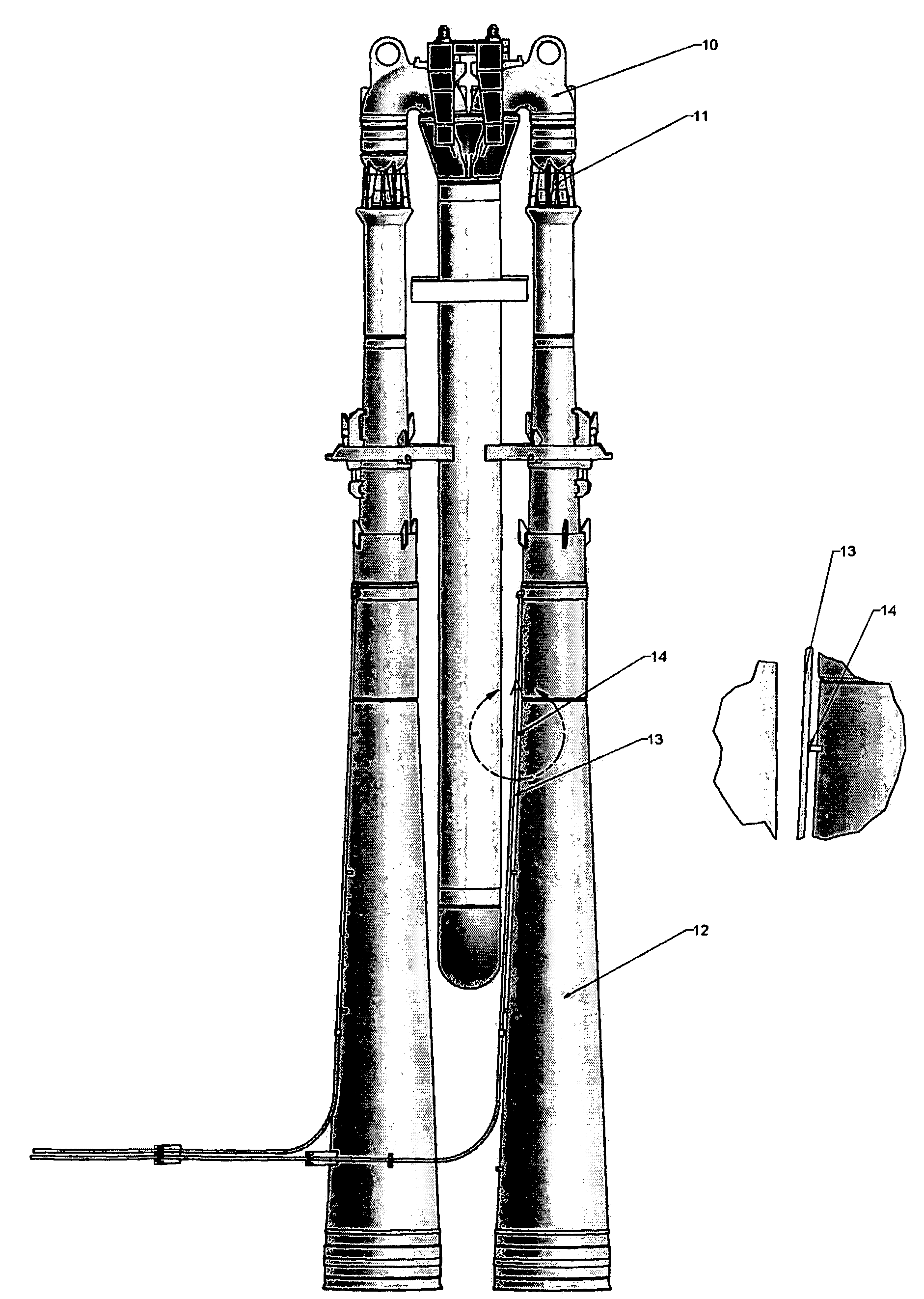
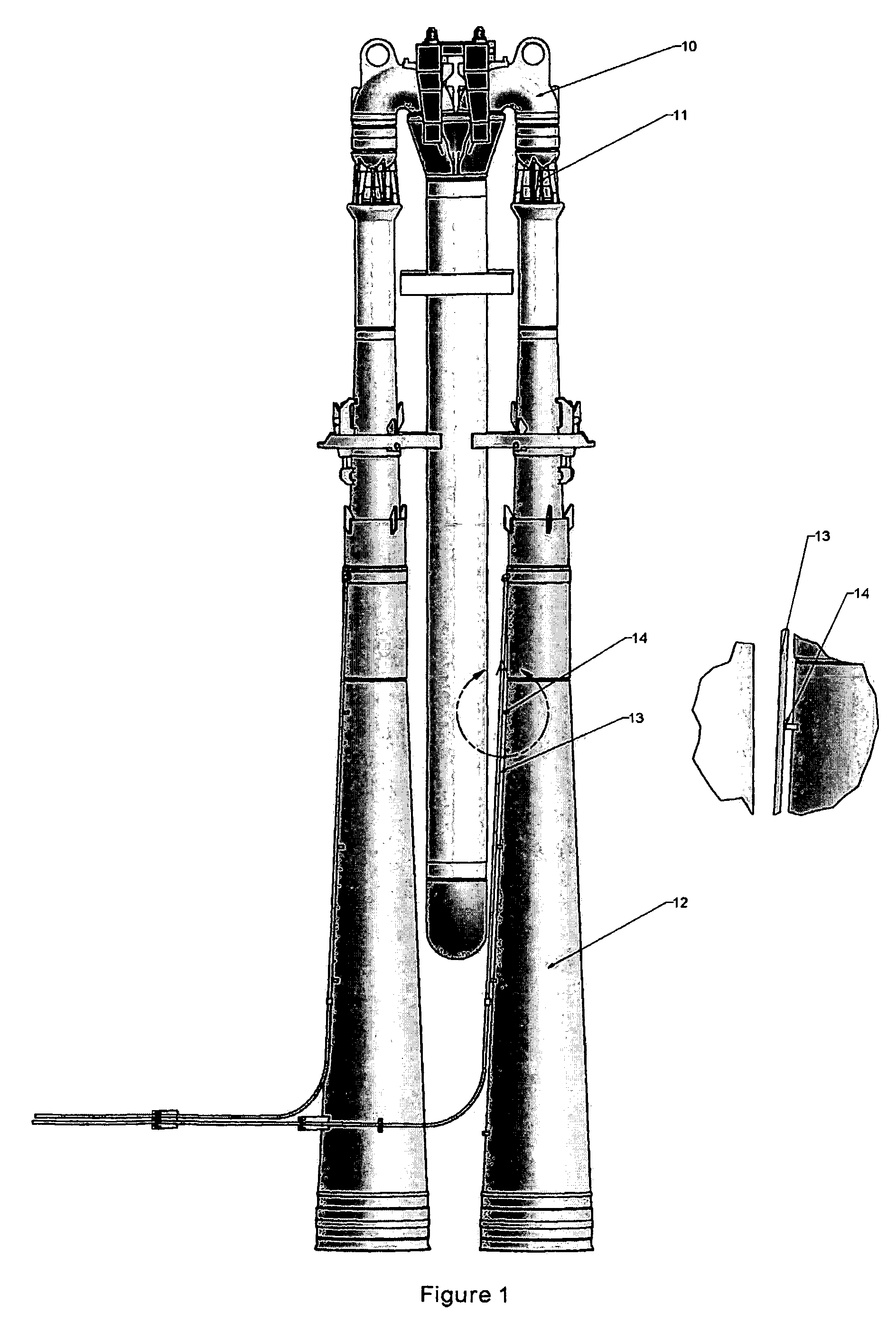
[0011]The jet pumps are located in the annual between the core shroud and the reactor vessel wall. Each pair of jet pumps is supplied a driving force from the recirculation pump. The driving force is distributed to eight to twelve jet pumps. The flow is sensed in the jet pump via a pressure tap that is monitored outside of the reactor vessel.

[0012]Each jet pump assembly is composed of two jet pumps. Each jet pump includes of an inlet mixer 10, a nozzle assembly 11, a diffuser 12 and a sensing line 13. The sensing line is held off the diffuser by a set of standoffs 14.

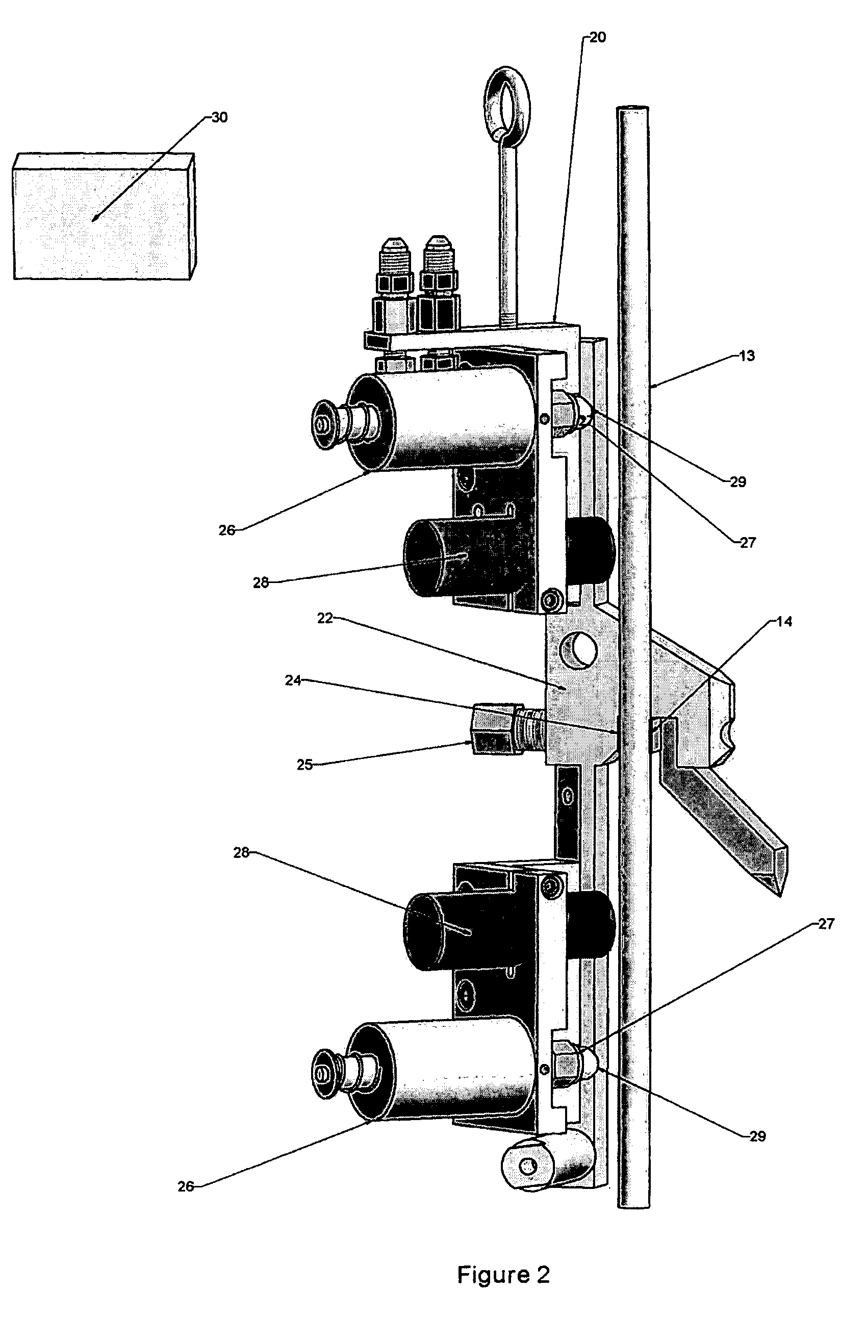
[0013]FIG. 2 illustrates a frequency measuring tool 20 for measuring a natural frequency of the reactor jet pump sensing line 13. The device 20 includes a base member 22, such as a stamped aluminum plate or the like, that supports the operating components of the device 20. A sensing line clamp 24 attaches the device 20 to the sensing line standoff 14. The sensing line clamp preferably hydraulically clamps to the sensing...


PUM

PropertyMeasurementUnit
natural frequencyaaaaaaaaaa
frequency measuringaaaaaaaaaa
frequencyaaaaaaaaaa

Abstract

A frequency measuring device measures a natural frequency of a reactor jet pump sensing line supported by a sensing line support bracket in a nuclear reactor. The frequency measuring device includes a base member, a sensing line clamp attached to the base member that attaches to the sensing line support bracket, and at least one actuator attached to the base member. The actuator is positioned relative to the sensing line when the sensing line clamp is attached to the sensing line so that the actuator can strike the sensing line. A proximity probe attached to the base member measures vibration of the sensing line and outputs a vibration signal. A processor receives and processes the vibration signal from the proximity probe to determine the natural frequency.

Description

BACKGROUND OF THE INVENTION[0001]The present invention relates to an on-site impact test to measure the natural frequencies of reactor components.[0002]As reactor recirculation pumps rotate, five vanes pass two cutwaters sequentially. Each time a vane passes the cutwater, the sudden change in fluid velocity causes pressure waves to be propagated upstream and downstream. Because the action of the two cutwaters occurs at exactly the same frequency, pressure waves from each cutwater add to form two pressure waves, one traveling upstream, and the other traveling downstream[0003]The frequency of these pressure waves is equal to the pump rotational speed times the number of vanes and is called the vane passing frequency (VPF). If the recirculation pump is operated such that the vane passing frequency coincides with the jet pump sensing line (JPSL) natural frequency, large amplification of sensing line motion will occur. If large amplification of the sensing line motion occurs due to near ...

Claims


Application Information

Patent Timeline
Patent Type & Authority Patents(United States)
IPC IPC(8): G01N29/04
CPCG01H1/06
Inventor KASIK, JAMESSUNDARAM, SWAMINATHAN H.
Owner GE HITACHI NUCLEAR ENERGY AMERICAS
Why Eureka
Try Eureka