Specimen transport system

a technology of transport system and rack, applied in the direction of charge manipulation, furniture, instruments, etc., can solve the problems of time-consuming, complicated configuration of its components, and complicated operation of the rack transfer device for lifting and moving the rack one after the other

Active Publication Date: 2009-08-25
IDS CO LTD
View PDF6 Cites 56 Cited by
  • Summary
  • Abstract
  • Description
  • Claims
  • Application Information

AI Technical Summary

Benefits of technology

[0009]An aspect of the invention is; a specimen transport system for transporting a specimen, comprising; a preceding section, a succeeding section located apart from the preceding section, a conveyor-type rack transport mechanism attached to the preceding section and / or the succeeding section and configured to transport a rack capable of holding a plurality of specimen containers which contain the specimen, and a car configured to travel between the preceding section and the succeeding section and provided with a conveyor-type rack transport mechanism configured to transport the rack capable of holding a plurality of specimen containers which contain the specimen.

Problems solved by technology

Since the specimen transport system described above uses the rack transfer device for rack movement, however, the configurations of its components are complicated.
Further, operation for rack movement such as to lift and move the racks one after another by the rack transfer device is complicated and time-consuming.

Method used


Image

  • Specimen transport system
  • Specimen transport system
  • Specimen transport system

Examples


first embodiment

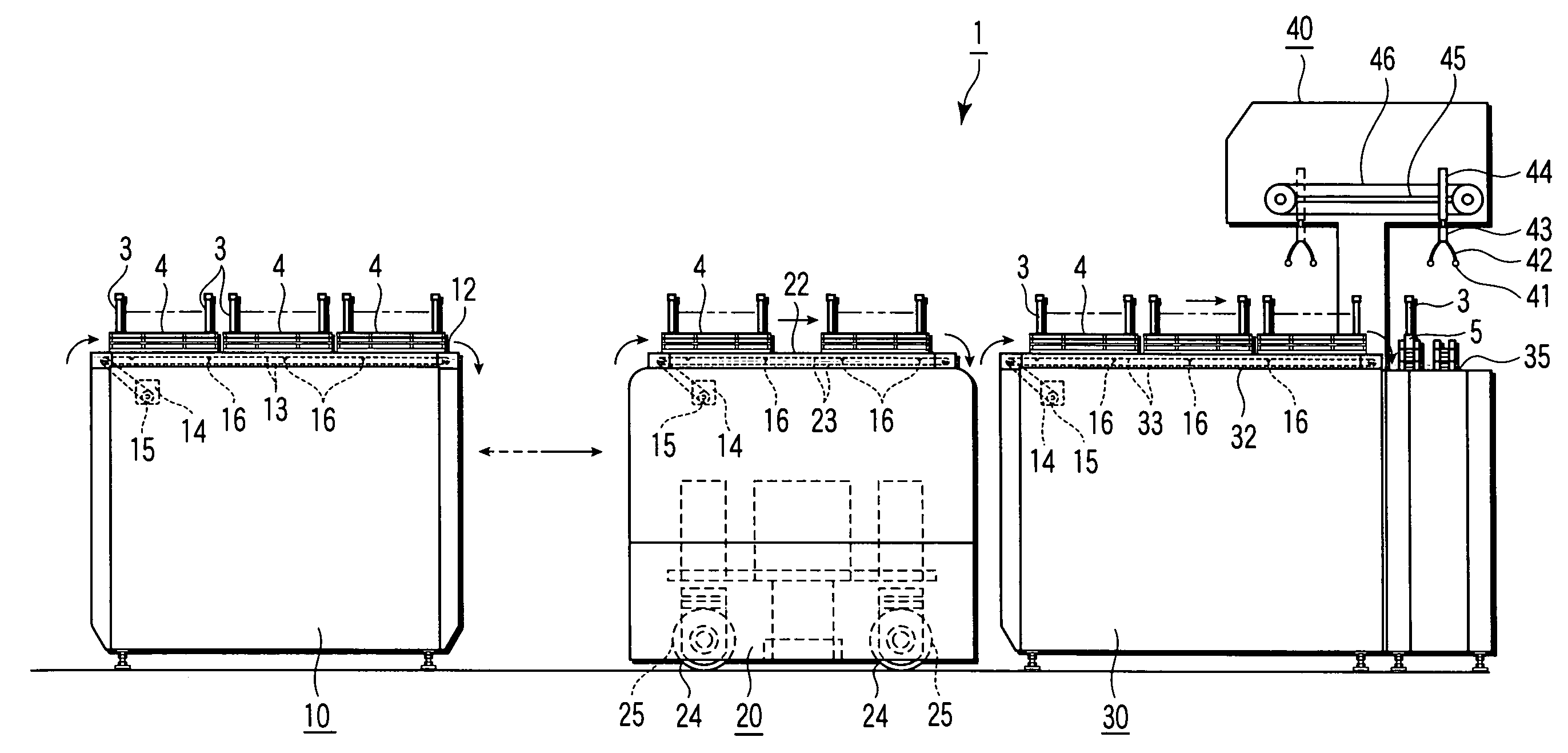
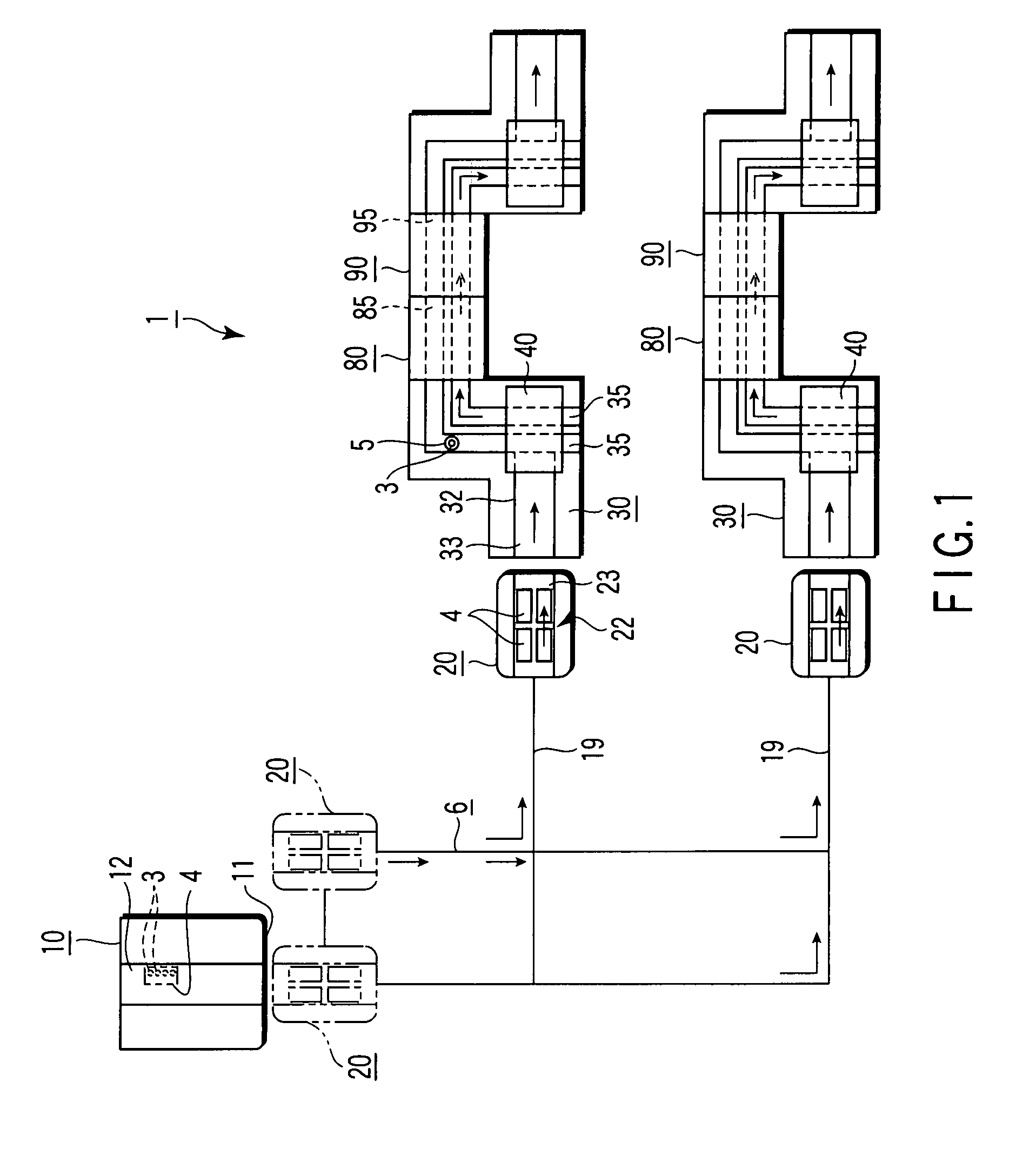
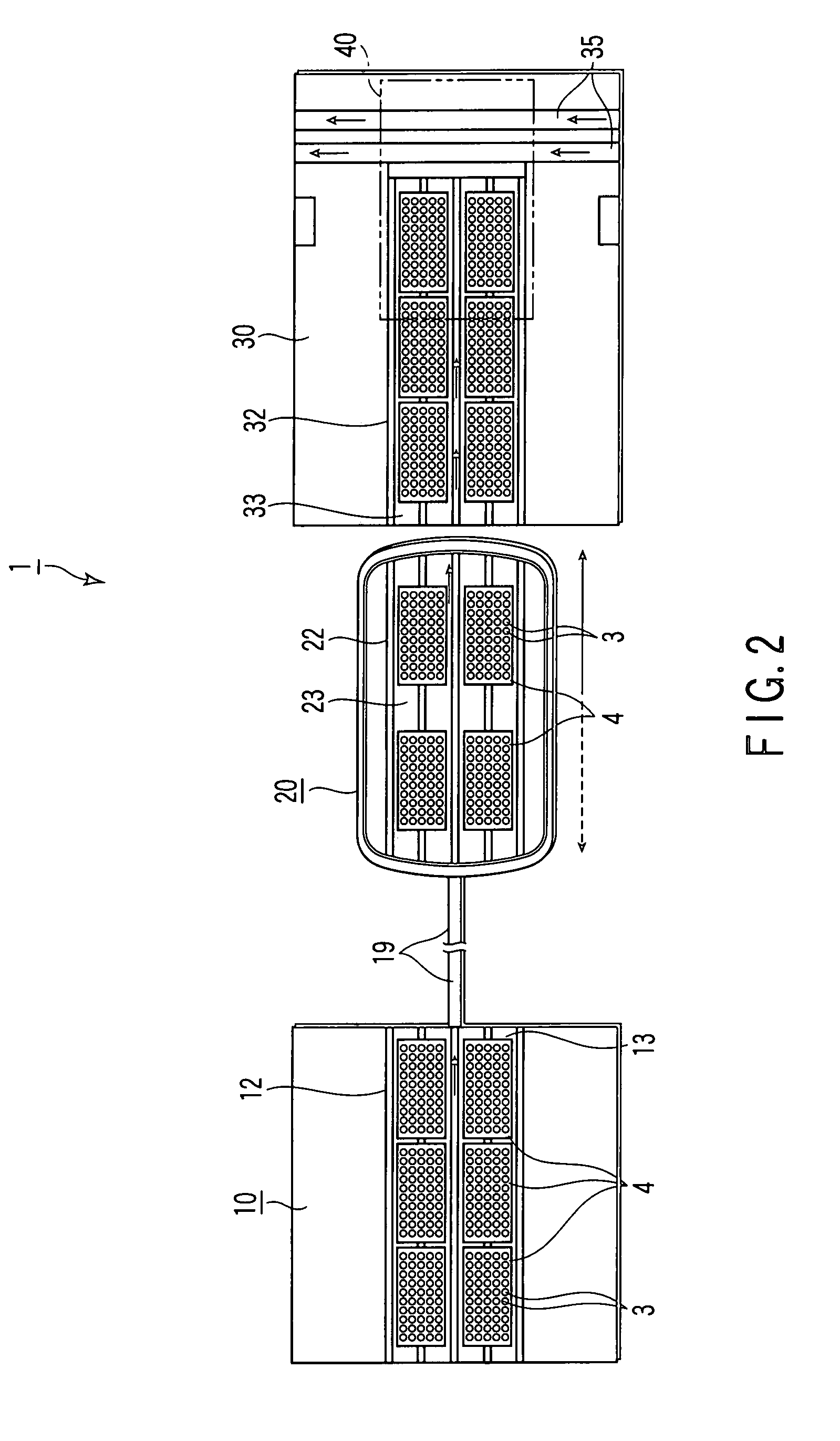
[0026]The following is a description of a specimen transport system 1 according to the present invention. FIG. 1 is a schematic plan view of the system 1 of the present embodiment. FIGS. 2 and 3 are schematic plan and side views, respectively, showing a part of the system 1. In each of these drawings, solid-line arrows indicate a transport direction, while broken-line arrows indicate a direction reverse to the transport direction. For ease of illustration, some configurations are shown in an enlarged or contracted manner or not shown in the drawings.

[0027]The specimen transport system 1 serves to transport specimen containers 3, which contain a specimen 2 such as blood, for each rack 4 or each specimen holder 5 in the arrowed transport direction along a transport line 6. The transport line 6 threads through specimen processing units 10 and 30 for variously processing the specimen, etc. The specimen transport system 1 comprises specimen processing units 10, 30, 80 and 90, including a...

second embodiment

[0053]A specimen transport system 101 according to the invention will now be described with reference to FIGS. 8 and 9.

[0054]In the present embodiment, a lift 50 is further located adjacent to the downstream side of a succeeding unit 30. The succeeding unit 30 of this embodiment is a specimen processing unit, such as a labeling unit, which is provided with a succeeding rack transport mechanism 32. The succeeding unit 30 is not provided with any holder transport mechanism, while the succeeding rack transport mechanism 32 is located extending between the opposite ends of the succeeding unit 30 in the transport direction.

[0055]The lift 50 is located adjacent to the downstream end of the succeeding unit 30 in the transport direction. The lift 50 is in the shape of a box having one open end face, and a liftable stage 51 is formed in the lift 50. A lift rack transport mechanism 52, which is constructed in the same manner as the aforementioned preceding rack transport mechanism, is provide...

third embodiment

[0059]A specimen transport system 111 according to the invention will now be described with reference to FIGS. 10 and 12.

[0060]In the present embodiment, a preceding unit 60 may be, for example, a dispensing unit or a labeling unit, which has a function to carry out specimen containers 3 for each rack, the containers being fed for each specimen holder 5 from various specimen processing units 80 and 90 on the upstream side in the transport direction of the preceding unit 60. A succeeding unit 70 is constructed in the same manner as the lift 50 according to the second embodiment.

[0061]The preceding unit 60 comprises a preceding holder transport mechanism 65 on the upstream side with respect to its transport direction. On the downstream side of the preceding unit 60, a preceding rack transport mechanism 62 extends from the vicinity of the downstream end of the transport mechanism 65 with respect to the transport direction to the downstream end of the preceding unit 60 with respect to t...


PUM


Abstract

A specimen transport system for transporting a specimen, includes, a preceding section, a succeeding section located apart from the preceding section, a conveyor-type rack transport mechanism attached to the preceding section and / or the succeeding section and configured to transport a rack capable of holding a plurality of specimen containers which contain the specimen, and a car configured to travel between the preceding section and the succeeding section and provided with a conveyor-type rack transport mechanism configured to transport the rack capable of holding a plurality of specimen containers which contain the specimen.

Description

CROSS-REFERENCE TO RELATED APPLICATIONS[0001]This application is based upon and claims the benefit of priority from prior Japanese Patent Application No. 2006-236940, filed Aug. 31, 2006, the entire contents of which are incorporated herein by reference.BACKGROUND OF THE INVENTION[0002]1. Field of the Invention[0003]The present invention relates to a specimen transport system for transporting a specimen by means of a car.[0004]2. Description of the Related Art[0005]A specimen transport system is a known technique in which a specimen, e.g., blood, in containers such as test tubes is transported by means of a car configured to travel between a preceding section and a succeeding section that are spaced apart from each other. This technique obviates the necessity of a transport mechanism that is dedicated to the movement of the specimen. As described in Jpn. Pat. Appln. KOKAI Publication No. 2005-300357, for example, one such specimen transport system is designed so that the specimen is...

Claims


Application Information

Patent Timeline
Patent Type & Authority Patents(United States)
IPC IPC(8): B65G47/34
CPCG01N35/04B01L9/06G01N33/49G01N35/00G01N35/02G01N35/10
Inventor ITOH, TERUAKI
Owner IDS CO LTD
Why Eureka
Try Eureka