LED light assembly with reflector having segmented curve section

a technology of reflectors and light assemblies, applied in the field of light assemblies, can solve the problems of poor optical efficiency of the lens-reflector system, detriment to directionality, etc., and achieve the effect of improving light collection efficiency and facilitating beam shaping

Active Publication Date: 2009-08-25
FEDERAL SIGNAL CORPORATION
View PDF23 Cites 43 Cited by
  • Summary
  • Abstract
  • Description
  • Claims
  • Application Information

AI Technical Summary

Benefits of technology

[0004]The invention provides a light assembly that can include an LED and a reflector. The LED is disposed with respect to the reflector such that an optical output axis of the LED is in offset, intersecting relationship to a principal axis of a reflective surface of the reflector such that the output axis is in non-parallel relationship with the principal axis of the reflective surface. The reflective surface can include a linear curved section. The curved section can be defined by a parabolic equation. The relationship between the LED and the reflective surface can facilitate beam shaping and improve light collection efficiency.
[0005]The reflector can take advantage of the directionality of the LED to orient and direct substantially all the light from the LED to the areas where it is desired and at light output levels appropriate to each area. As a result, the reflector design of the invention can have extremely high optical efficiency.

Problems solved by technology

This directionality has been a detriment when trying to couple LEDs with conventional parabolic reflectors.
These LED-lens-reflector systems can suffer from poor optical efficiency.

Method used


Image

  • LED light assembly with reflector having segmented curve section
  • LED light assembly with reflector having segmented curve section
  • LED light assembly with reflector having segmented curve section

Examples


Embodiment Construction

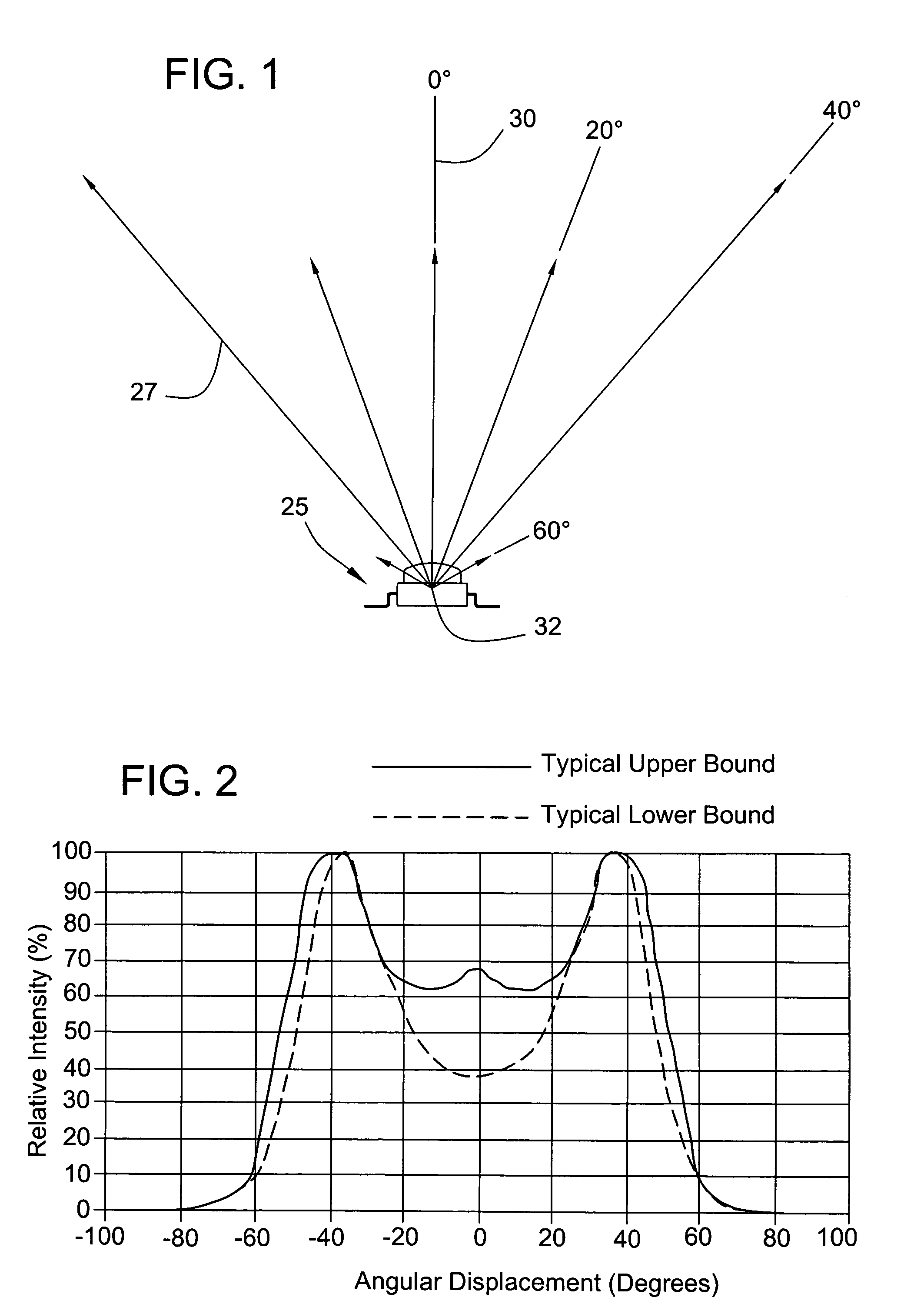
[0031]Referring to FIGS. 1 and 2, the spatial radiation pattern from a typical high output LED 25, in this case a Lumileds Luxeon® LED, along with a graphical representation of the light output of the LED 25 is shown by way of a plurality of arrows 27 with the length of the arrow 27 corresponding to the relative light intensity output for the LED at that location. The radiation pattern clearly demonstrates that the highest light output occurs at approximately 40° from both directions from an optical output axis 30 of the LED (shown in FIGS. 1 and 2 as a 0° axis), and that the majority of the light is produced within 60° from both directions from the output axis 30. The output axis 30 can extend substantially through the center of the face of the lens of the LED through a virtual focal point 32 of the LED. Since the die that produces the light in the LED is a finite size, the virtual focal point 32 can be a theoretical point within the LED where the majority of the light rays being e...


PUM


Abstract

A light assembly is disclosed which can include an LED array and a reflector. The LED array can include a plurality of LEDs which are disposed such that each LED is substantially aligned to define a focal axis. Each LED can emit light substantially along an optical output axis, with each optical output axis being perpendicular to the focal axis. The optical output axis of the LED array can be disposed in intersecting relationship with the reflector surface. The reflector can be defined by a curve section defined with respect to a principal axis. The principal axis and the output axis of the LED array can be in non-parallel relationship with each other. The optical output axis of the LED array can be substantially perpendicular to the principal axis of the curve section of the reflector.

Description

CROSS-REFERENCE TO RELATED APPLICATIONS[0001]This application claims the benefit of U.S. Provisional Patent Application No. 60 / 510,192 filed Oct. 10, 2003, which is incorporated in its entirety herein by this reference.FIELD OF THE INVENTION[0002]This invention relates in general to light assemblies, and more particularly to a light assembly which includes a light-emitting diode (LED).BACKGROUND OF THE INVENTION[0003]The light output of an LED can be highly directional. This directionality has been a detriment when trying to couple LEDs with conventional parabolic reflectors. The directionality of an LED, taken together with the desire to shape the light output in different and sometimes opposite ways to yield a desired performance specification, has resulted in LED lighting systems that frequently employ lens elements in addition to reflectors to shape the beam. These LED-lens-reflector systems can suffer from poor optical efficiency. U.S. Pat. No. 6,318,886 describes a method wher...

Claims


Application Information

Patent Timeline
Patent Type & Authority Patents(United States)
IPC IPC(8): F21V13/00F21S4/00F21S8/10F21V7/00F21V7/04F21V7/06F21V7/09F21V29/00
CPCF21S4/008F21V7/0008F21V7/04F21V7/06F21V7/09F21Y2103/003F21S48/1317F21S48/215F21S48/218F21S48/23F21S48/328F21V7/005F21V29/004F21Y2101/02F21S48/10F21V29/70F21S4/28F21Y2103/10F21Y2115/10F21S41/143F21S41/148F21S41/151F21S41/153F21S41/321F21S41/323F21S41/332F21S43/13F21S43/14F21S43/15F21S43/30F21S43/31F21S45/47F21S41/00
Inventor CZAJKOWSKI, ROBERT A.
Owner FEDERAL SIGNAL CORPORATION
Why Eureka
Try Eureka