Mixer assembly for combustor of a gas turbine engine having a plurality of counter-rotating swirlers

a gas turbine engine and swirler technology, applied in the direction of engine ignition, engine starter, lighting and heating apparatus, etc., can solve the problems of reducing the production of undesirable combustion products, reducing the power output, and difficult to achiev

Active Publication Date: 2009-09-01
GENERAL ELECTRIC CO
View PDF10 Cites 44 Cited by
  • Summary
  • Abstract
  • Description
  • Claims
  • Application Information

AI Technical Summary

Benefits of technology

[0016]In accordance with an eighth embodiment of the present invention, a method of operating a gas turbine engine combustor with reduced emissions, wherein said combustor includes a pilot mixer and a main mixer, is disclosed as including the following steps: providing a swirler arrangement in flow communication with an annular cavity of the main mixer, wherein an intense mixing region is created adjacent a plurality of fuel injection ports to the annular cavity; causing air supplied to the swirler arrangement to swirl in a counter-rotating manner in the annular cavity; allocating air supplied to the swirler arrangement among each swirler thereof in a predetermined amount; and, providing fuel from the fuel injection ports into the intense mixing region.

Problems solved by technology

Balancing the operation of a combustor to allow efficient thermal operation of the engine, while simultaneously minimizing the production of undesirable combustion products, is difficult to achieve.
In that regard, operating at low combustion temperatures to lower the emissions of NOx can also result in incomplete or partially incomplete combustion, which can lead to the production of excessive amounts of HC and CO, as well as lower power output and lower thermal efficiency.

Method used


Image

  • Mixer assembly for combustor of a gas turbine engine having a plurality of counter-rotating swirlers
  • Mixer assembly for combustor of a gas turbine engine having a plurality of counter-rotating swirlers
  • Mixer assembly for combustor of a gas turbine engine having a plurality of counter-rotating swirlers

Examples


second embodiment

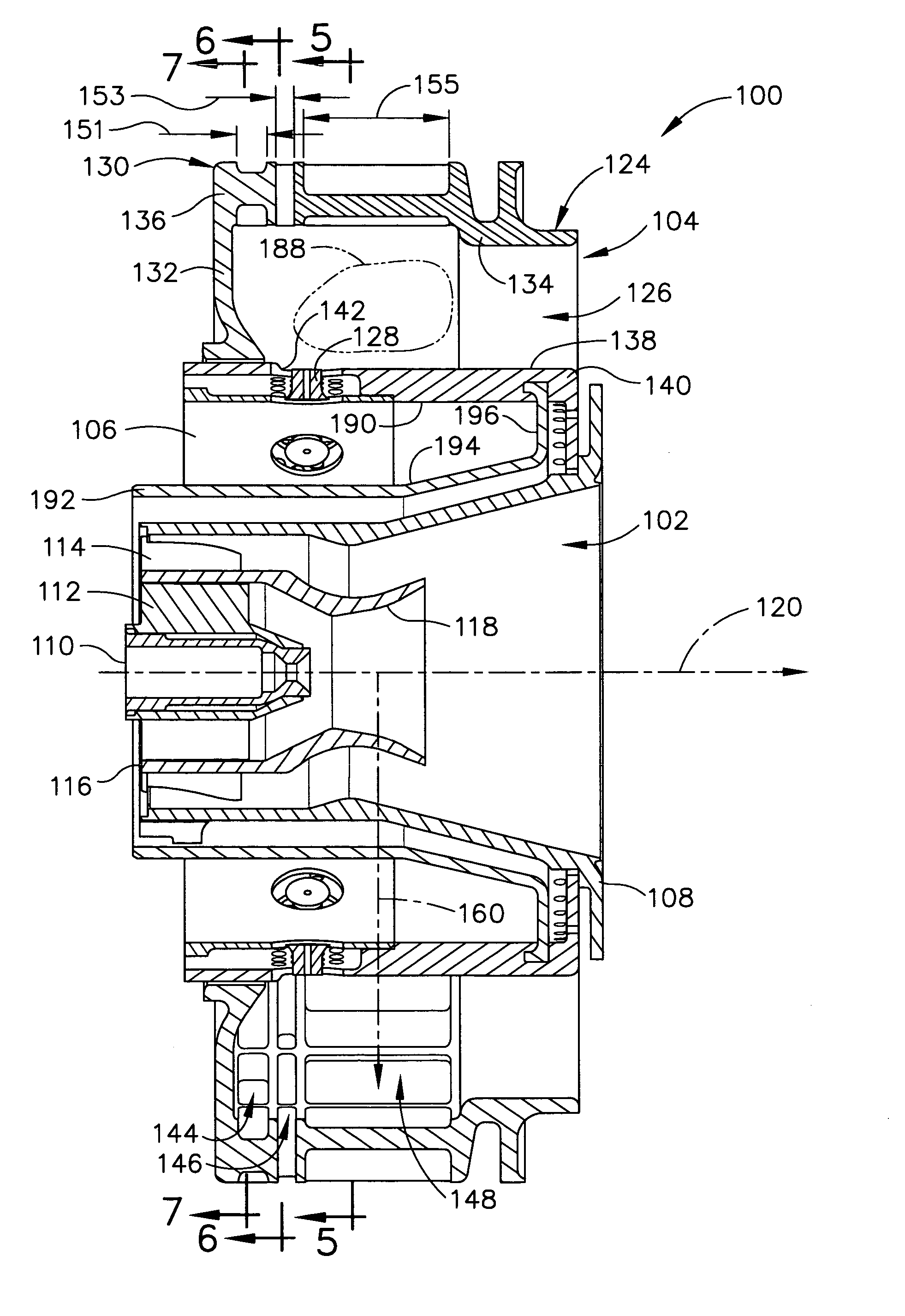
[0085]In the mixing assembly, identified by numeral 200, an alternative swirler arrangement 202 having a swirler housing 203 is utilized and shown in FIGS. 8-12. Since each swirler is preferably oriented at an acute angle (approximately 0-60°) to centerline axis 120 through mixer assembly 200, it will be seen that swirler housing 203 includes a conical wall 205 oriented at an acute angle which forms part of annular cavity 126 of main mixer 104. As further seen therein, swirler arrangement 202 preferably includes first, second and third swirlers 204, 206 and 208, respectively, positioned upstream from fuel injection ports 128. First swirler 204 is positioned adjacent forward wall 132, second swirler 206 is positioned immediately downstream of first swirler 204, and third swirler 208 is positioned immediately downstream of second swirler 206. In addition, each swirler has a plurality of vanes (identified by numerals 210, 212 and 214 for first swirler 204, second swirler 206, and third...

third embodiment

[0095]In the mixing assembly, identified by numeral 300, an alternative swirler arrangement 302 having a swirler housing 303 is utilized and shown in FIGS. 13-19. It will be seen that swirler arrangement 302 preferably includes first, second and third swirlers 304, 306 and 308, respectively, positioned upstream from fuel injection ports 128. First swirler 304 is located within a forward wall 305 of swirler housing 303 and oriented substantially parallel to centerline axis 120 through mixing assembly 300. Second swirler 306 is located within a forward wall 305 of swirler housing 303, oriented substantially parallel to centerline axis 120, and positioned radially outside of first swirler 304. Third swirler 308 is located within radially outer wall 134 of swirler housing 303 and is oriented substantially perpendicular to centerline axis 120. Each swirler has a plurality of vanes (identified by numerals 310, 312 and 314 for first swirler 304, second swirler 306, and third swirler 308, r...

fourth embodiment

[0105]In the mixing assembly, identified by numeral 400, an alternative swirler arrangement 402 having a swirler housing 403 is utilized and shown in FIGS. 20-27. It will be seen that swirler arrangement 402 preferably includes first, second, third and fourth swirlers 404, 406, 408 and 411, respectively, positioned upstream from fuel injection ports 128. First and second swirlers 404 and 406 are positioned within a forward wall 405 and oriented substantially parallel to centerline axis 120 of mixing assembly 400, with second swirler 406 being positioned radially outside of first swirler 404. Third and fourth swirlers 408 and 411 are positioned within outer wall 134 and oriented substantially perpendicular to centerline axis 120 along an axis 409, with fourth swirler 411 being located downstream of third swirler 408. In addition, each swirler has a plurality of vanes (identified by numerals 410, 412, 414 and 416 for first swirler 404, second swirler 406, third swirler 408 and fourth ...


PUM


Abstract

A mixer assembly for use in a combustor of a gas turbine engine, including a pilot mixer, a main mixer, and a fuel manifold positioned between the pilot mixer and the main mixer. The pilot mixer further includes an annular pilot housing having a hollow interior and a pilot fuel nozzle mounted in the pilot housing and adapted for dispensing droplets of fuel to the hollow interior of the pilot housing. The main mixer further includes a main housing surrounding the pilot housing and defining an annular cavity, a plurality of fuel injection ports for introducing fuel into the cavity, and a swirler arrangement including at least three swirlers positioned upstream from the plurality of fuel injection ports, wherein each swirler of the swirler arrangement has a plurality of vanes for swirling air traveling through the respective swirler to mix air and the droplets of fuel dispensed by the fuel injection ports. The swirlers are oriented substantially radially to a centerline axis through the mixer assembly or at an acute angle to the centerline axis through the mixer assembly. Alternatively, at least two swirlers are included substantially parallel to the centerline axis through the mixer assembly along with one or more radial or conical swirlers. In another alternative, the swirler arrangement includes a first swirler oriented substantially parallel to a centerline axis through the mixer assembly, a second swirler oriented at an acute angle to the centerline axis through the mixer assembly, and a third swirler oriented substantially radially to the centerline axis through the mixer assembly.

Description

BACKGROUND OF THE INVENTION[0001]The present invention relates to a staged combustion system in which the production of undesirable combustion product components is minimized over the engine operating regime and, more particularly, to a swirler arrangement for the main mixer of such system which enhances mixing of fuel and air.[0002]Air pollution concerns worldwide have led to stricter emissions standards both domestically and internationally. Aircraft are governed by both Environmental Protection Agency (EPA) and International Civil Aviation Organization (ICAO) standards. These standards regulate the emission of oxides of nitrogen (NOx), unburned hydrocarbons (HC), and carbon monoxide (CO) from aircraft in the vicinity of airports, where they contribute to urban photochemical smog problems. Such standards are driving the design of gas turbine engine combustors, which also must be able to accommodate the desire for efficient, low cost operation and reduced fuel consumption. In addit...

Claims


Application Information

Patent Timeline
Patent Type & Authority Patents(United States)
IPC IPC(8): F02C1/00
CPCF23R3/14F23R3/343F23R3/286Y02T50/675Y02T50/60
Inventor HSIEH, SHIH-YANGHSIAO, GEORGE CHIA-CHUNLI, SHUI-CHIMONGIA, HUKAM CHAND
Owner GENERAL ELECTRIC CO
Why Eureka
Try Eureka