Automatic universal multi-purpose ground stand

a multi-purpose, universal technology, applied in the direction of machine supports, drilling machines, manufacturing tools, etc., can solve the problems of difficult to firmly secure the umbrella stand, the stand is not able to accommodate any type of umbrella or other device, and the use of anchor screws, etc., to achieve convenient and convenient use, simple materials, and high mobility and useful

Inactive Publication Date: 2009-09-01
SARAF JAMES
View PDF20 Cites 14 Cited by
  • Summary
  • Abstract
  • Description
  • Claims
  • Application Information

AI Technical Summary

Benefits of technology

[0017]A further object of the present invention is to provide a portable, extremely mobile universal automatic multi-purpose ground stand that may be quickly and easily secured into a malleable surface by any person lacking the motor skills and / or motor strength to secure a traditional umbrella stand.
[0018]Still another object of this invention is to provide a universal automatic multi-purpose ground stand unit that comprises relatively simple materials, is relatively lightweight and durable, and is relatively simple to manufacture.

Problems solved by technology

Any person who has tried to place an umbrella in the sand at a beach on a windy day knows that it is quite difficult to firmly secure the umbrella stand so that the umbrella does not, almost immediately tip over.
While there are many stands available on the market today none of these devices automatically screw the stand into the ground, nor are the stands available today able to accommodate any type of umbrella or other device such as a fishing pole.
He does not teach the use of a anchor screw, nor does he use a DC motor.
This apparatus is basically a tripod stand and does not teach the use of a helical anchor screw, nor is it a motorized, automatic securement device.
Although there are ground stands in prior art, none of the foregoing patents combine, a helical anchor screw, a DC motor for automatic securement, and the ability to attach a variety of devices to the stand, such as an umbrella or a fishing pole.

Method used


Image

  • Automatic universal multi-purpose ground stand
  • Automatic universal multi-purpose ground stand
  • Automatic universal multi-purpose ground stand

Examples


Embodiment Construction

[0027]The terminology used herein should be interpreted in its broadest reasonable manner, even though it is being utilized in conjunction with a detailed description of a certain specific preferred embodiment of the present invention. This is further emphasized below with respect to some particular terms used herein. Any terminology that the reader should interpret in any restricted manner will be overtly and specifically defined as such in this specification. The preferred embodiment of the present invention will now be described with reference to the accompanying drawings, wherein like reference characters designate like or similar parts throughout.

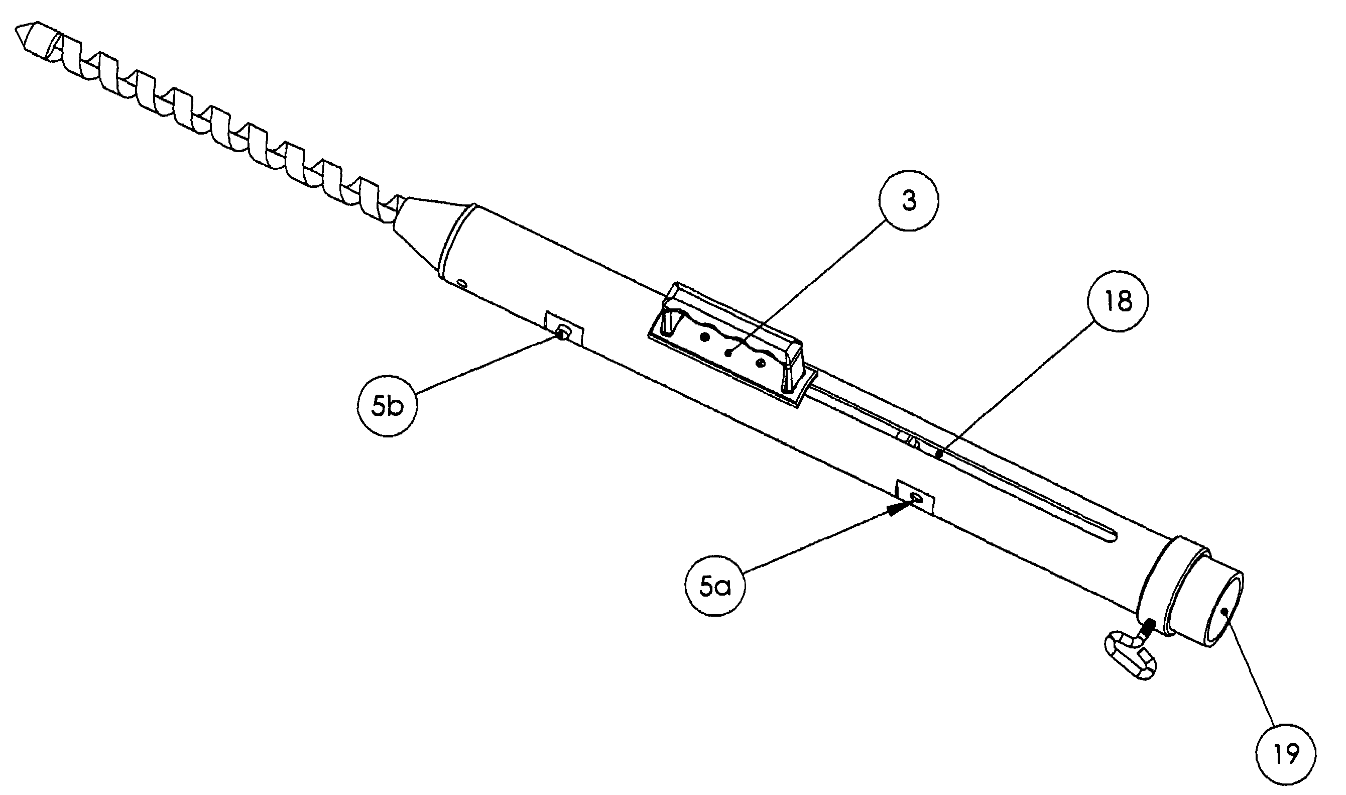
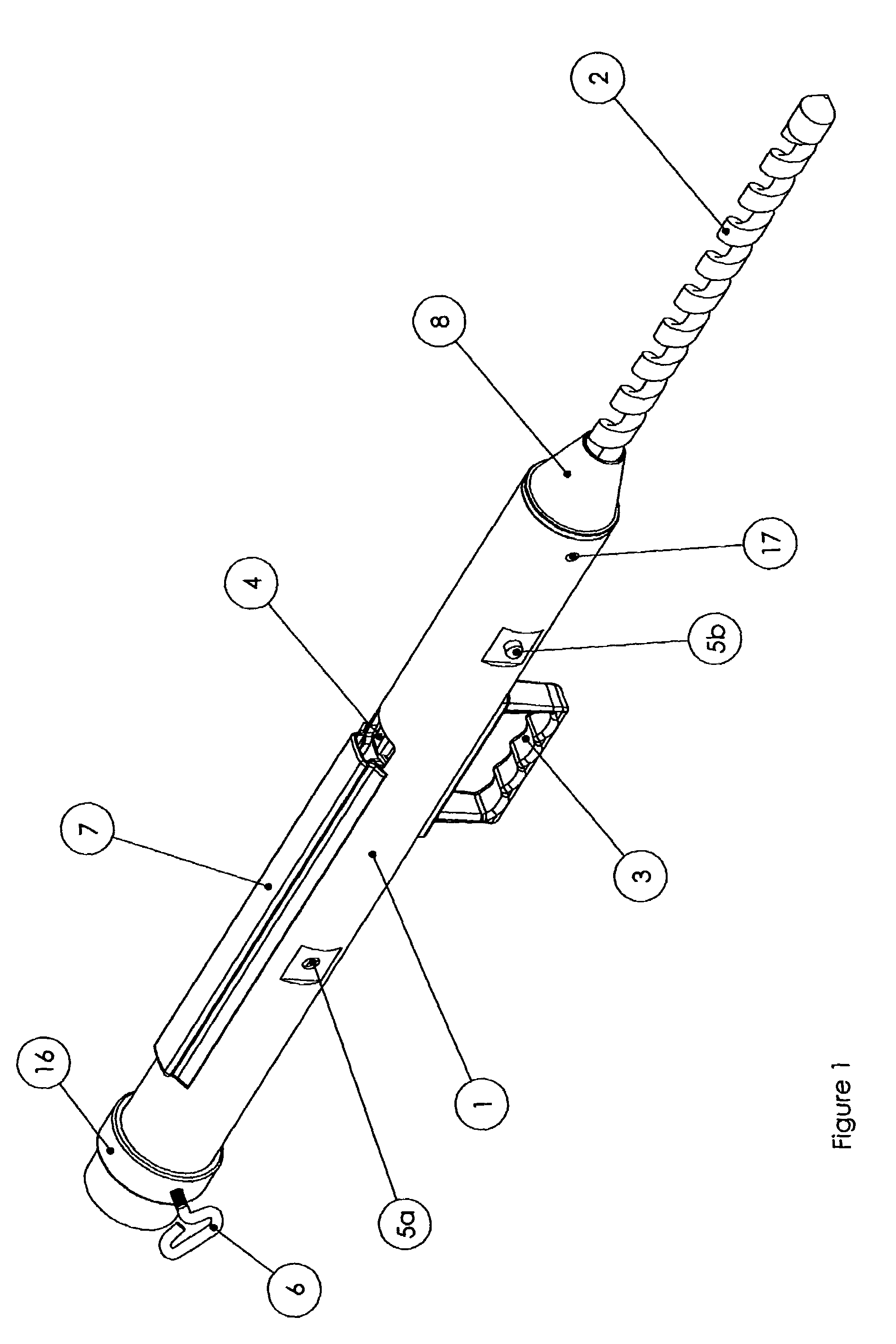
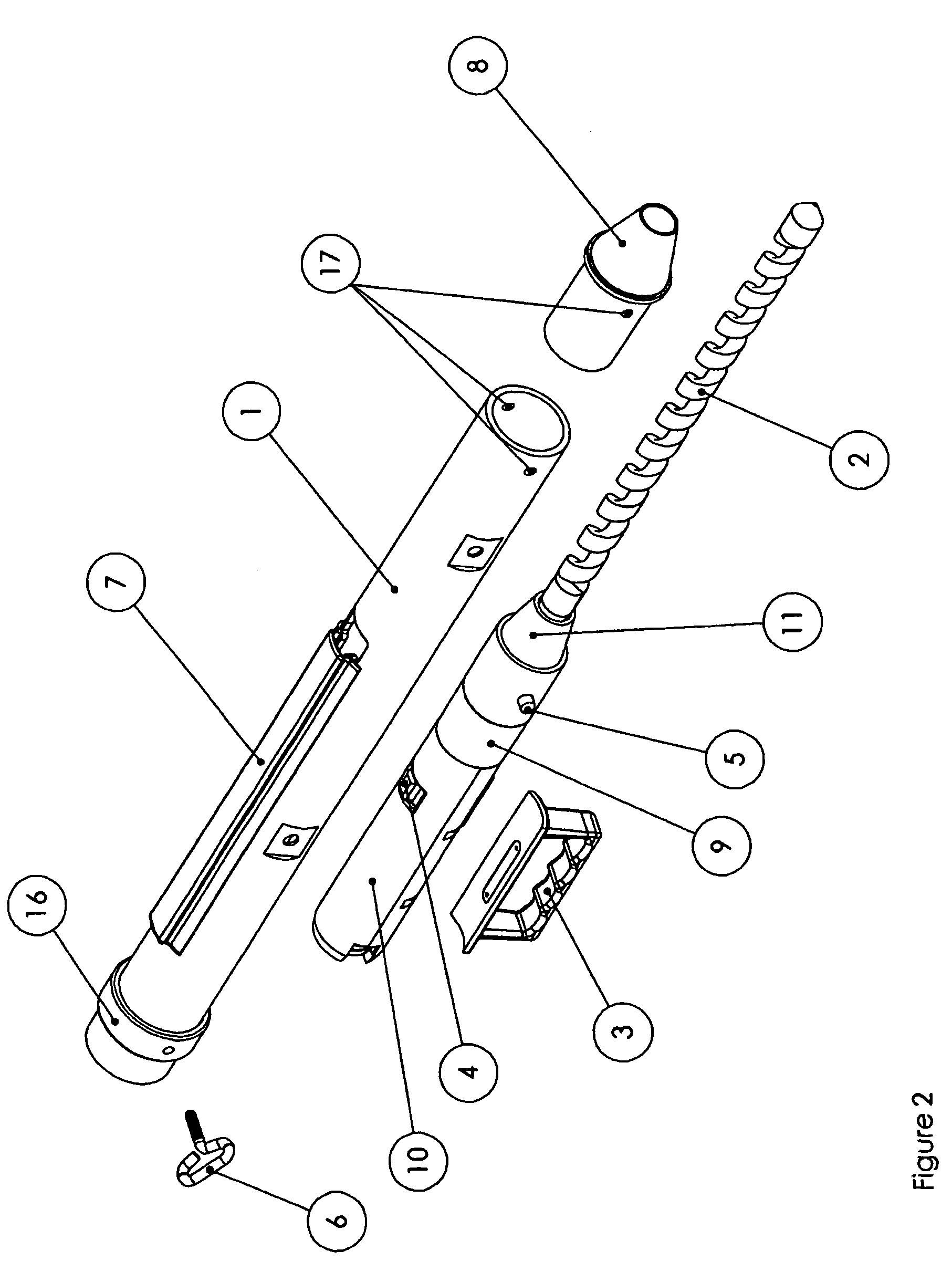
[0028]FIGS. 1-6 illustrate an automatic, universal, multi-purpose ground stand. The basic components of this design are the main tube 1 as shown in FIG. 1 and FIG. 2, the helical anchor screw 2, as shown in FIGS. 1-5, and the power drive 10 as shown in FIG. 2 and in more detail in FIG. 3. Each major component will be discussed in turn....


PUM

PropertyMeasurementUnit
power driveaaaaaaaaaa
diameteraaaaaaaaaa
strengthaaaaaaaaaa

Abstract

An automatic, universal, multi-purpose ground stand to securely affix an umbrella, or any like device, into any malleable surface such as sand, grass, gravel or dirt. The device is intended to accommodate any size or shape of commercially available beach or sun umbrellas. This device also contemplates the securement of other devices such as fishing poles. The device is comprised, primarily, of a main tube with a helical auger screw bit and a DC electric motor to turn the screw. A user of said device would extend the helical auger screw bit, engage the DC electric motor, and allow the action of the DC electric motor to secure the helical auger screw into a malleable surface.

Description

BACKGROUND OF INVENTION[0001]This invention relates to a universal, automatic, multi-purpose ground stand. The inventor first intended this stand to be used with any beach umbrella. Any person who has tried to place an umbrella in the sand at a beach on a windy day knows that it is quite difficult to firmly secure the umbrella stand so that the umbrella does not, almost immediately tip over. While there are many stands available on the market today none of these devices automatically screw the stand into the ground, nor are the stands available today able to accommodate any type of umbrella or other device such as a fishing pole. Thus, it would be highly desirable, and especially for those people with limited strength, to have a solution that addresses the need to securely and firmly screw a multi-purpose stand into the ground.[0002]Various stands exist in prior art. Stands intended primarily for umbrella securement are generally not motorized. Additionally, many of the umbrella sta...

Claims


Application Information

Patent Timeline
Patent Type & Authority Patents(United States)
IPC IPC(8): F16M13/00A45B1/00A45B23/00A45F3/44E04H12/22
CPCE04H12/2223A45B23/00Y10T408/65
Inventor SARAF, JAMES
Owner SARAF JAMES
Why Eureka
Try Eureka