Locating device

a technology of locating device and magnetic field, which is applied in the direction of magnetic variable, using reradiation, instruments, etc., can solve the problems of user loss of information about absolute signal strength, difficult to locate, and difficult to display the dynamic of this type of signal strength, and achieve the effect of higher sensitivity

Active Publication Date: 2009-09-01
ROBERT BOSCH GMBH
View PDF7 Cites 16 Cited by
  • Summary
  • Abstract
  • Description
  • Claims
  • Application Information

AI Technical Summary

Benefits of technology

[0008]The locating device according to the present invention advantageously enables at least two dynamic ranges to be displayed via its output unit when reading an output variable correlated with the measuring signal of the existing sensor. The display area of the output unit provided in the device may therefore be fully utilized, making it very easy to detect the location of the maximum measuring signal.
[0009]To improve the displayability of the measuring signal demonstrating a high level of dynamics, it is advantageous to equip the locating device with a first and at least one second dynamic range, the at least one second dynamic range having a higher sensitivity of the output variable correlated with the measuring signal in relation to the measuring signal. This makes it possible, using the first dynamic range, to carry out a rough measurement and, in the range of maximum values for the output variable correlated with the measuring signal, to actively switch to a second dynamic range, i.e., in a manner controlled by the user. Because, when using the second dynamic range, the output variable of the locating device has a higher sensitivity toward the measuring signal, the determination of the absolute maximum of the measuring signal, and thus the precise location of the enclosed object generating the measuring signal, is guaranteed.
[0010]It is advantageously possible to design the output unit of the measuring device so that the output variable correlated with the measuring signal is displayed in the first and in at least one second dynamic range at the same time.
[0011]The output variable of the locating device correlated with the measuring signal is therefore advantageously displayed visually, in particular via a display provided in the measuring device. The visual display of the output variable correlated with the measuring signal makes it possible to show the measuring signal simultaneously in a display of the first dynamic range and in a display of the second dynamic range at higher sensitivity.
[0012]In alternative embodiments of the measuring device according to the present invention, the output variable correlated with the measuring signal is advantageously displayable alternately in either the first dynamic range or at least one second dynamic range, depending on the requirements. For this purpose, the locating device according to the present invention has switching means which enable the user to switch back and forth between the at least two dynamic ranges or to use both dynamic ranges in parallel. In this manner, it is possible to manually adjust the sensitivity of a measurement to the current strength of the existing measuring signal and thus achieve a fine output resolution for the output variable correlated with the measuring signal. The advantage of a manual sensitivity adjustment lies in the fact that full use of the output unit provided in the locating device, which may advantageously be a visual display, may be made. This makes it substantially easier to accurately determine the precise position and, if necessary, even the center of an object, for example a metal or wooden object, since the latter corresponds to the maximum of the measuring signal. A sensitivity setting designed in such a user-friendly manner unmistakably provides the user with full control over the device and gives him / her the information he / she needs without requiring any complicated or incomprehensible control elements.
[0014]In an embodiment of the locating device according to the present invention, it is possible to assign the at least one second dynamic range to a discrete output value of the first dynamic range for the purpose of representing the output variable correlated with the measuring signal. In particular, it is advantageous to select the size of the second dynamic range so that it corresponds to the dynamic range of only one segment in the display of the first dynamic range of the output unit. This provides the user of the locating device according to the present invention with a kind of “zoom function” which transfers the strength of the output variable in the first dynamic range of the output unit to a second dynamic range for the output unit, using a higher sensitivity:

Problems solved by technology

The enormous dynamics of the sensors used, which occur despite calibration of the measuring device, present a problem that arises, in particular, with inductive and capacitive locating devices.
Due to the limited display area of the locating devices according to the related art, dynamics of this type are difficult to display.
However, the disadvantage of a display of this type is that weak or even very strong objects appear at the beginning and end of the dynamic range of the displayed scale and are therefore very difficult to locate, since the changes shown in the measuring device display are too small.
In addition, the user loses the information about the absolute signal strength.

Method used


Image

  • Locating device
  • Locating device
  • Locating device

Examples


Embodiment Construction

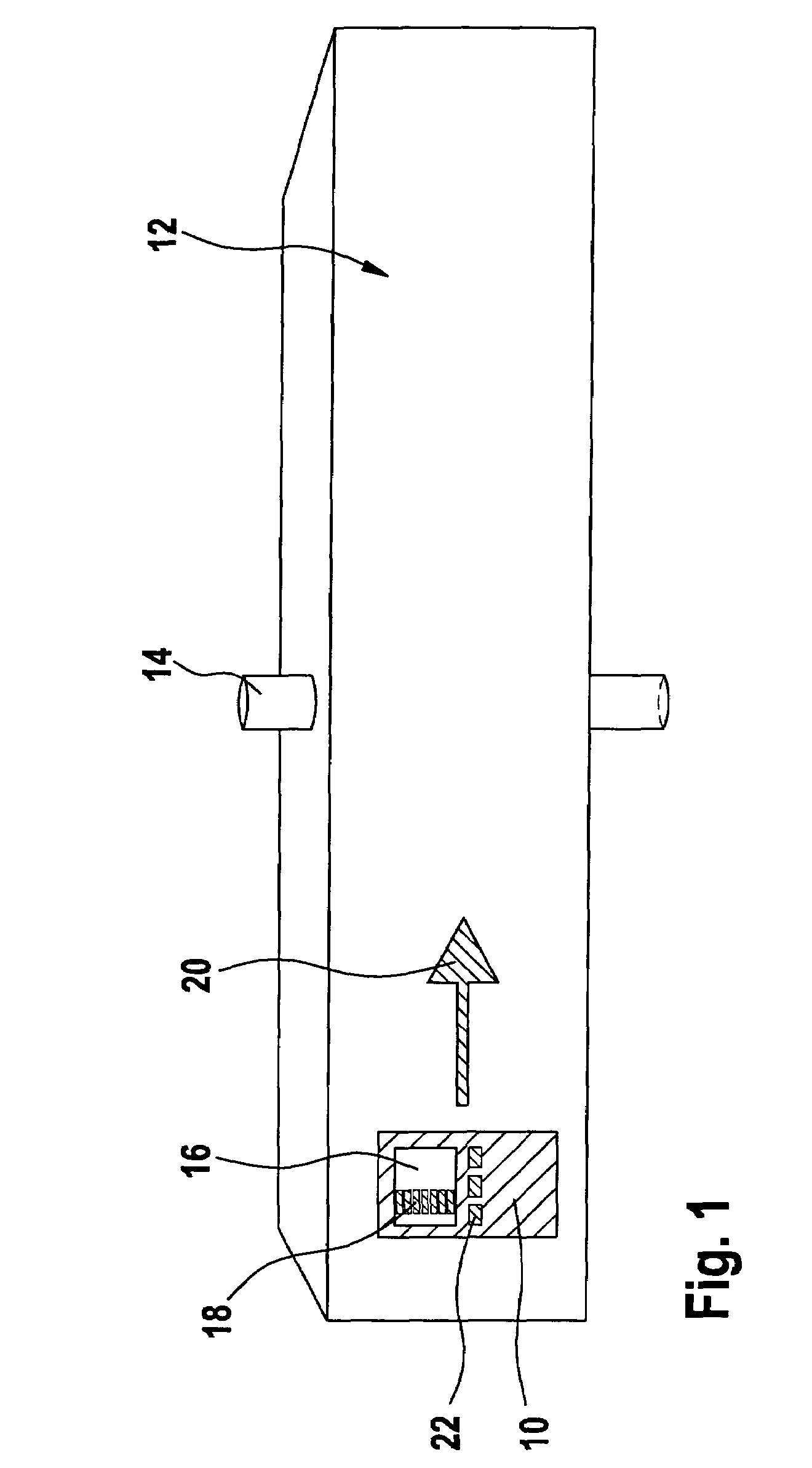
[0018]FIG. 1 shows a typical measurement situation for a locating device. Locating device 10 is passed over the surface of a medium 12 to be examined which may be, for example, a wall, a floor or the ceiling of a building, to thereby detect the position of an object 14 enclosed in medium 12. An object of this type may be, for example, an electrical wire, pipes such as water pipes, metal bars, wooden beams or other objects.

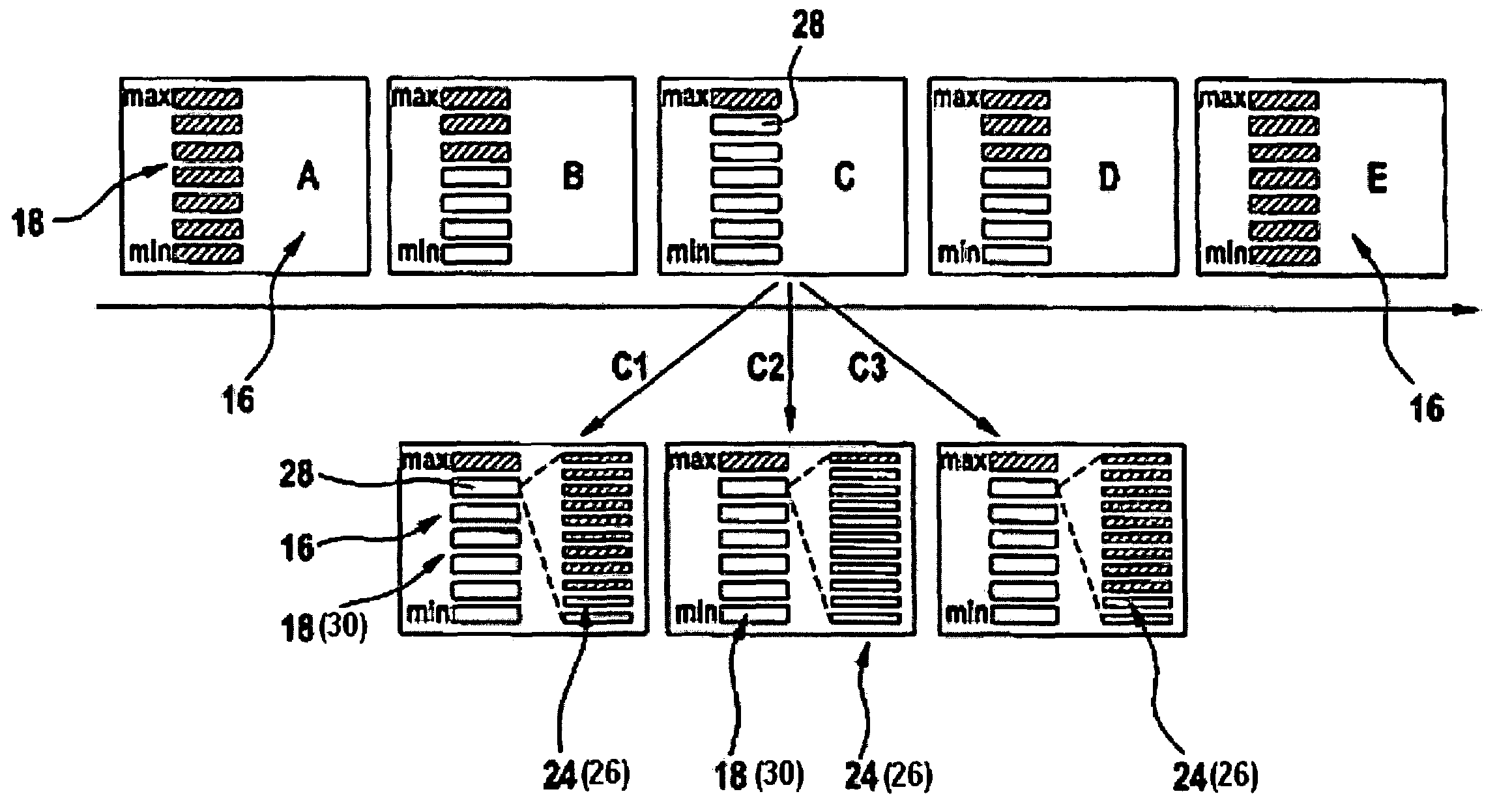
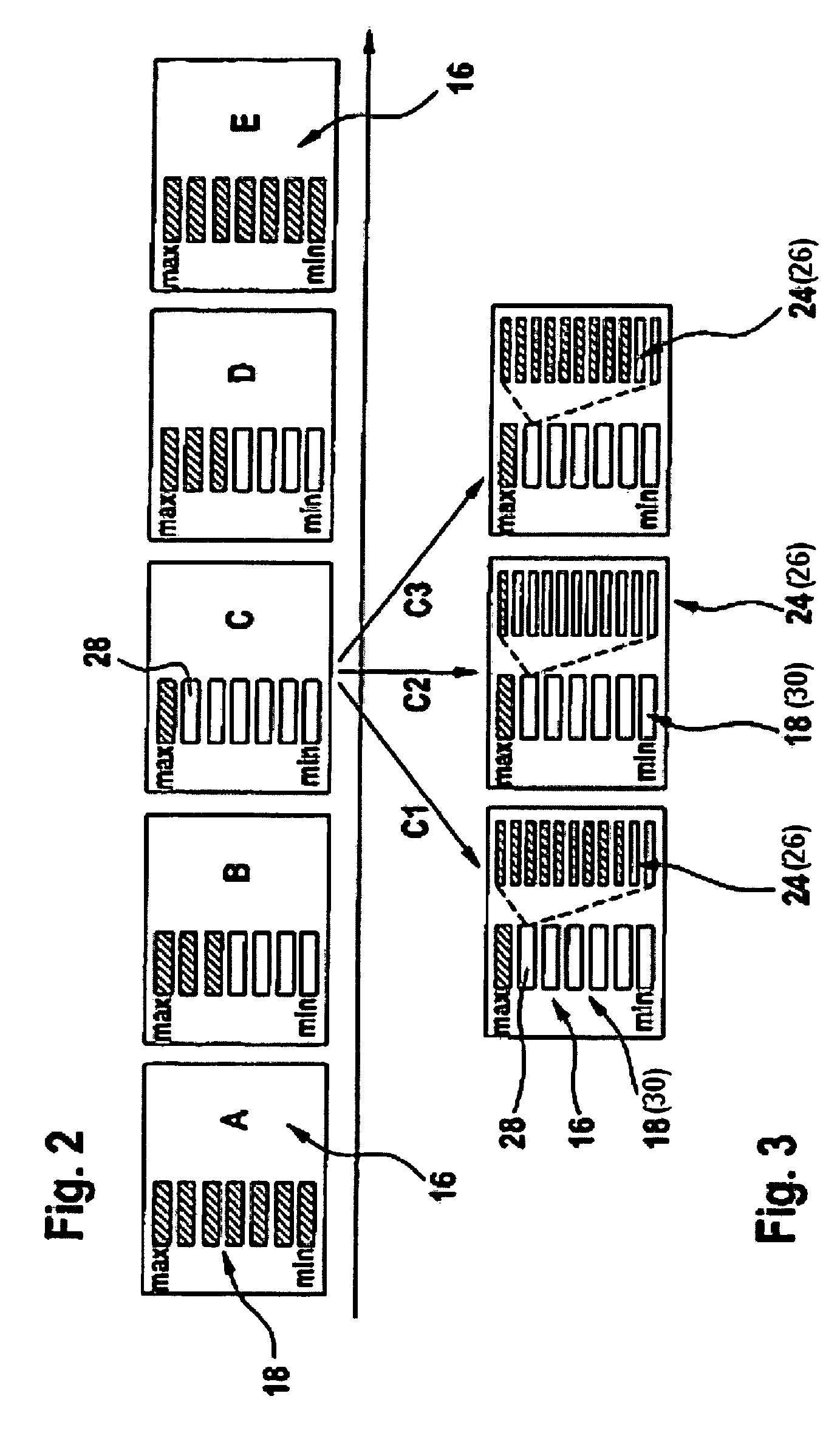
[0019]Locating device 10 according to the present invention has, in particular, an inductive and a capacitive sensor which make it possible to locate and perhaps even identify an object 14 enclosed in medium 12 on the basis of the magnetic or electrical fields generated by the sensors. In addition to corresponding control electronics, the appropriate power supply system and an evaluation unit for the detected measuring signal, locating device 10 according to the present invention has, in the exemplary embodiment according to FIG. 1, a graphical display 16 which dis...


PUM


Abstract

A locating device, in particular a hand-held locating device, for detecting objects enclosed in a medium, including an output unit for displaying at least one output variable correlated with a measuring signal of at least one sensor of the locating device, the output unit having a first dynamic range for displaying the output variable correlated with the measuring signal. At least one further dynamic range having a changed sensitivity compared to the first dynamic range is displayable via the display unit.

Description

FIELD OF THE INVENTION[0001]The present invention relates to a locating device, in particular a hand-held locating device, for detecting objects enclosed in a medium.BACKGROUND INFORMATION[0002]Locating devices are used to detect, for example wires, pipes, metal bars, wooden beams or other objects embedded in walls, ceilings or floors. Inductive devices, among other things, are used, i.e., devices that generate a magnetic field which is disturbed by the metallic objects enclosed in a medium. In addition to the inductive devices, capacitive devices, line voltage detectors and high-frequency detectors are also used.[0003]Most of these devices must be calibrated when powered on or at regular intervals. For this purpose, an internal electronic adjustment is usually carried out which must take place in a measurement environment in which no objects to be located may be present close to the measuring device sensor. For example, metal locating devices must be calibrated at a great distance ...

Claims


Application Information

Patent Timeline
Patent Type & Authority Patents(United States)
IPC IPC(8): G01V3/11G01V3/15
CPCG01V3/15
Inventor SKULTETY-BETZ, UWEHAASE, BJOERNKRAPF, REINER
Owner ROBERT BOSCH GMBH
Why Eureka
Try Eureka