Safety switch

a safety switch and switch technology, applied in the field of safety switches, can solve the problems of increased product cost and dangerous events, and achieve the effect of reducing manufacturing costs and less number of parts

Inactive Publication Date: 2009-09-01
YU TSUNG MOU
View PDF38 Cites 6 Cited by
  • Summary
  • Abstract
  • Description
  • Claims
  • Application Information

AI Technical Summary

Benefits of technology

[0007]The main objective of the present invention is to provide a switch which provides a sufficient space for movement of the operation member to ensure the contact plate to be deformed completely to cut off the circuit.
[0010]Yet another objective of the present invention is to provide a switch that includes less number of parts so as to have lower manufacturing cost.

Problems solved by technology

There are too many parts involved in the safety switch and a longer period of time is required when assembling the switch, this increases the cost of the product.
The re-connect action might generate sparks which could cause dangerous events.

Method used


Image

  • Safety switch
  • Safety switch
  • Safety switch

Examples


Embodiment Construction

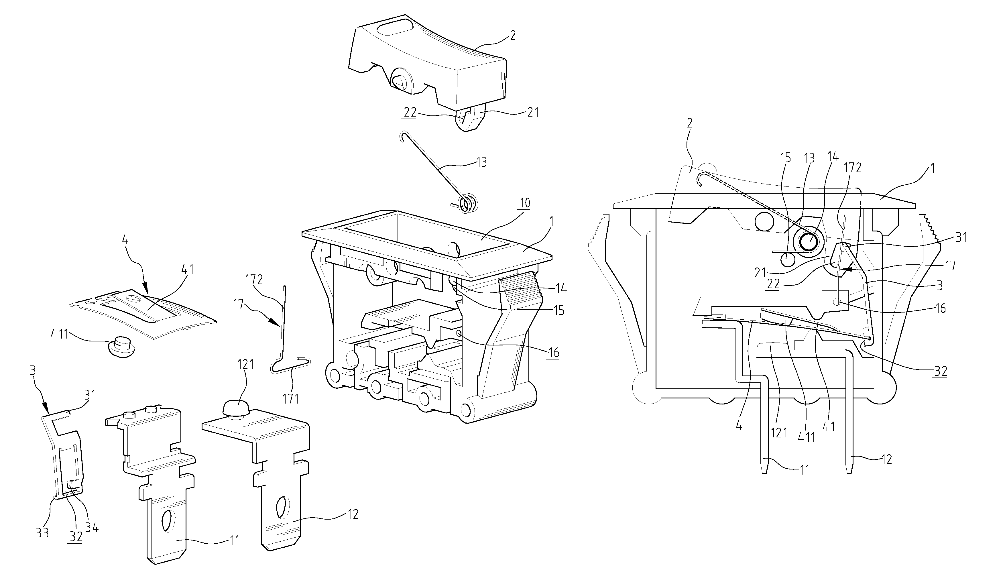
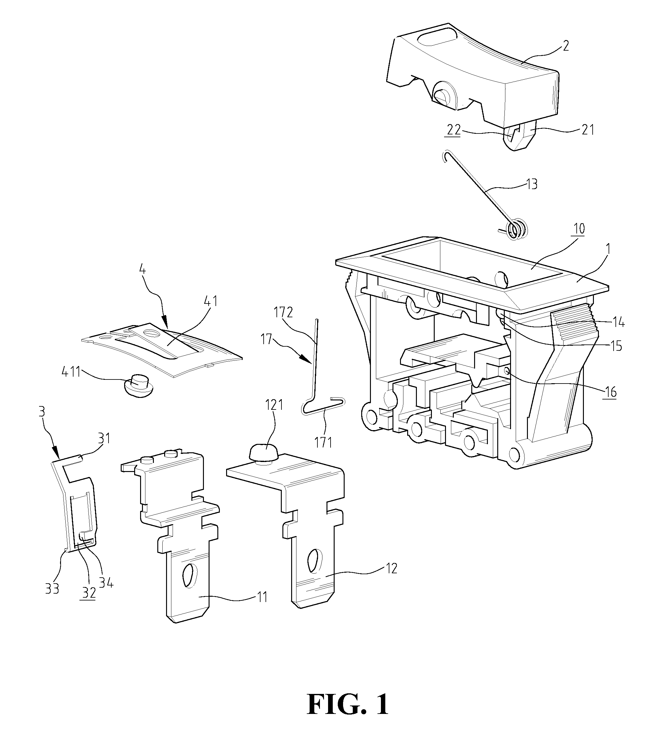
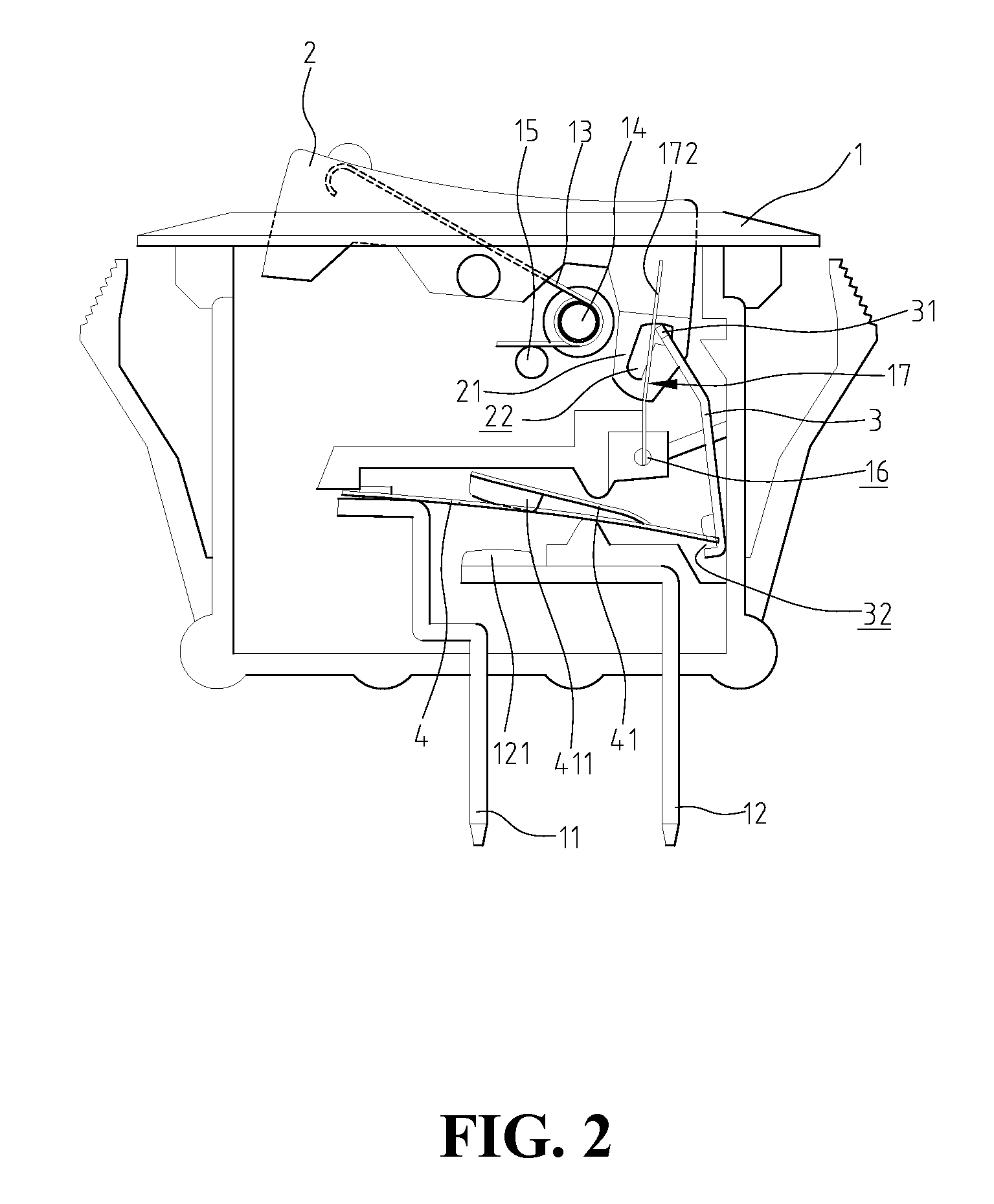
[0018]Referring to the drawings and in particular to FIGS. 1 and 2, a switch in accordance with the present invention comprises a body 1 with a top opening 10, and a switch member 2 pivotally engaged with the top opening 10 of the body 1. An extension 21 extends from an underside of a first end of the switch member 2, and a substantially inverted L-shaped slot 22 is defined through the extension 21. The slot 22 includes a horizontal space and a vertical space. The switch member 2 is pivoted about the pivots on two sides of the mediate portion thereof. A torsion spring 13 is connected to the inside of the body 1, and includes a coil portion and two legs extended from the coil portion. The coil portion is mounted to a first rod 14 extending from the inside of the body 1 and one of the two legs is biased against a second rod 15 extending from the inside of the body 1. The other one of the two legs contacts the underside of a second end of the switch member 2. By the torsion spring 13, ...


PUM


Abstract

A switch includes a body with a switch member on a top thereof, an extension extends from an underside of the switch member, and a substantially inverted L-shaped slot is defined through the extension. Two terminals extend through a bottom of the body, in which one of the terminals is fixed with a contact plate. The contact plate has a tongue with a free end, which contacts the other terminal when the circuit is ON, and is separated from the other terminal when the circuit is OFF. An operation member has a first end movably engaged with the slot and a second end connected with the contact plate. A positioning member having a first end pivotally connected to an inside of the body and a second end biasing the first end of the operation member. Under the current overload condition, the switch member is pivoted by a torsion spring to the OFF position.

Description

BACKGROUND OF THE INVENTION[0001]1. Field of the Invention[0002]The present invention relates to a safety switch that ensures the switch member to be pivoted automatically to “OFF” position under the current overload condition and the switch can be installed in any desired angle.[0003]2. The Prior Arts[0004]Each of U.S. Pat. Nos. 5,262,748, 4,167,720, 4,937,548, 5,223,813, 5,451,729 and 5,558,211 disclosed a safety switch and each of these safety switches uses a bi-metallic plate to prevent from being burn under the current overload condition. The bi-metallic plate is deformed when an overloading occurs so as to separate the two contact points respectively located on the bi-metallic plate and one of the two terminals. Some inherent shortcomings for these conventional safety switches are found. There are too many parts involved in the safety switch and a longer period of time is required when assembling the switch, this increases the cost of the product. The parts might be arranged i...

Claims


Application Information

Patent Timeline
Patent Type & Authority Patents(United States)
IPC IPC(8): H01H71/16H01H71/58
CPCH01H23/24H01H37/54H01H77/04H01H37/74
Inventor YU, TSUNG MOU
Owner YU TSUNG MOU
Why Eureka
Try Eureka