Ultrasonic sensor

a technology of ultrasonic and sensor, applied in the field of ultrasonic sensors, can solve the problems of corrosion on the surface, dents on the vibrating surface,

Inactive Publication Date: 2009-09-01
DENSO CORP
View PDF20 Cites 6 Cited by
  • Summary
  • Abstract
  • Description
  • Claims
  • Application Information

AI Technical Summary

Benefits of technology

[0006]It is an object of the present invention to provide an ultrasonic sensor less subject to damage and corrosion.
[0008]Under this structure, the film can help prevent hitting stones from damaging the vibrating planar member, so that the surface of the vibrating planar member is protected from being damaged and corroded.

Problems solved by technology

Further, the ultrasonic sensor is attached to the bumper or regions around the bumper, so thrown stones or gravels often hit the sensor to cause dents on the surface of the vibrating planar member.
These dents or damages then bring about corrosion on the surface.

Method used


Image

  • Ultrasonic sensor
  • Ultrasonic sensor
  • Ultrasonic sensor

Examples


Embodiment Construction

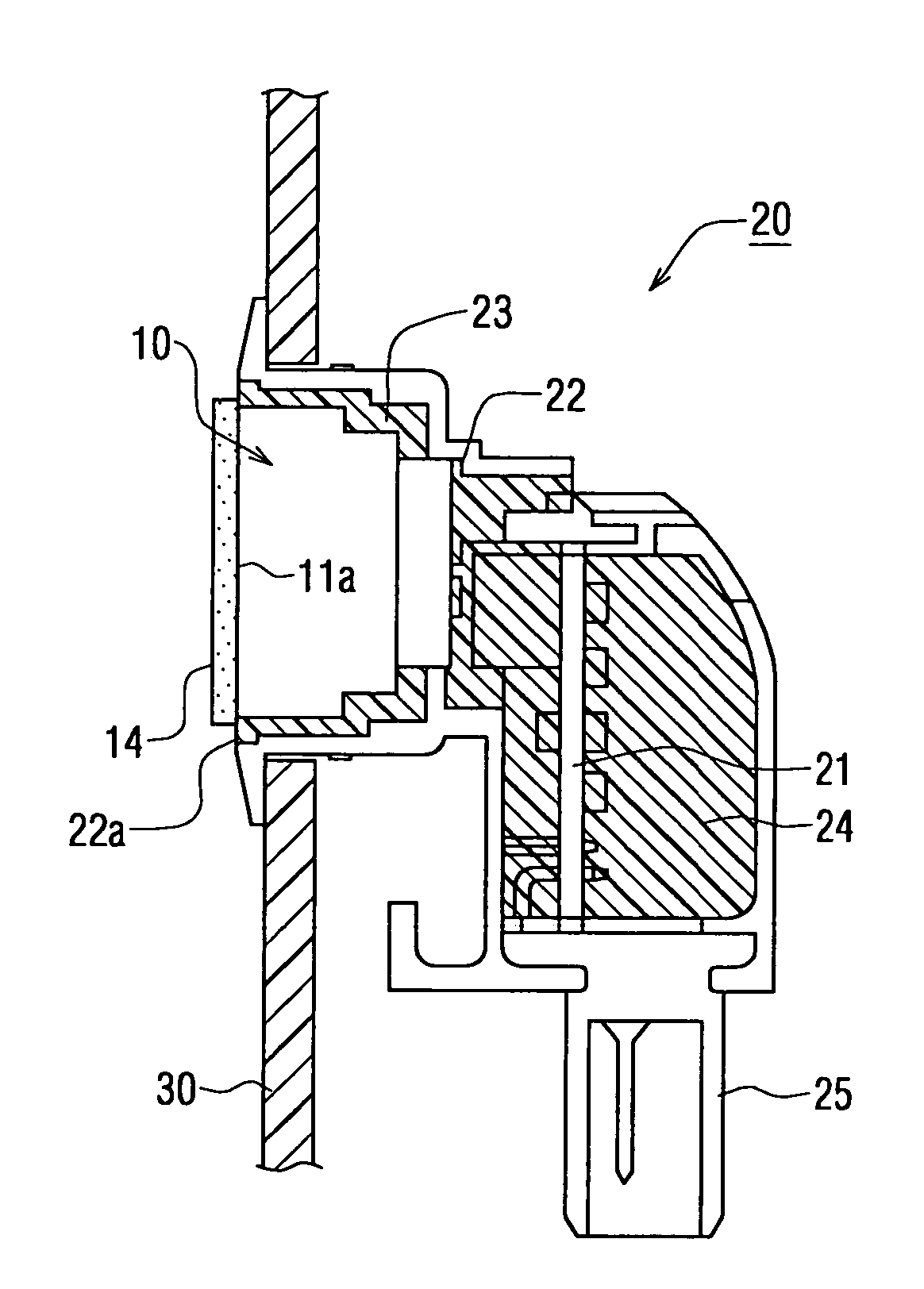
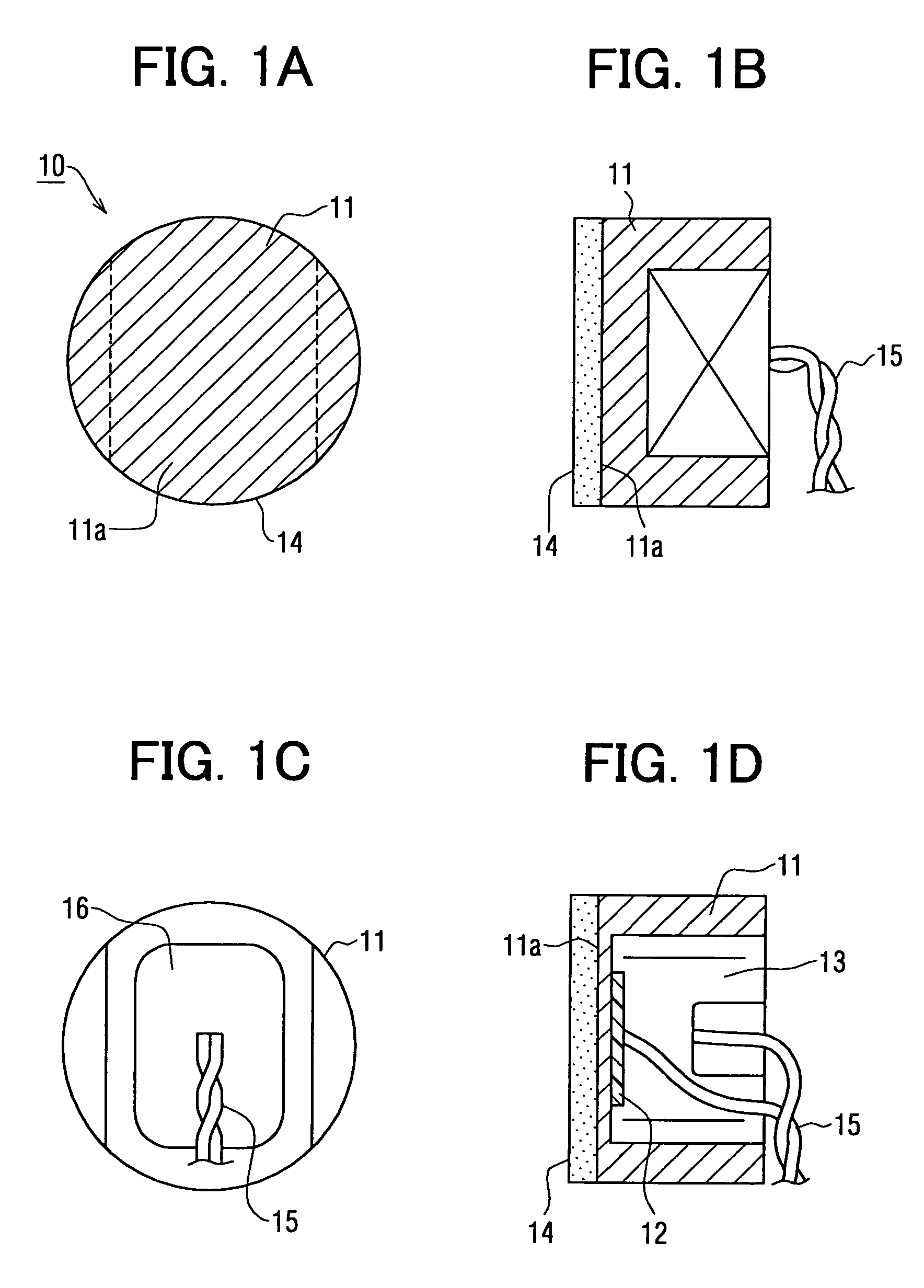
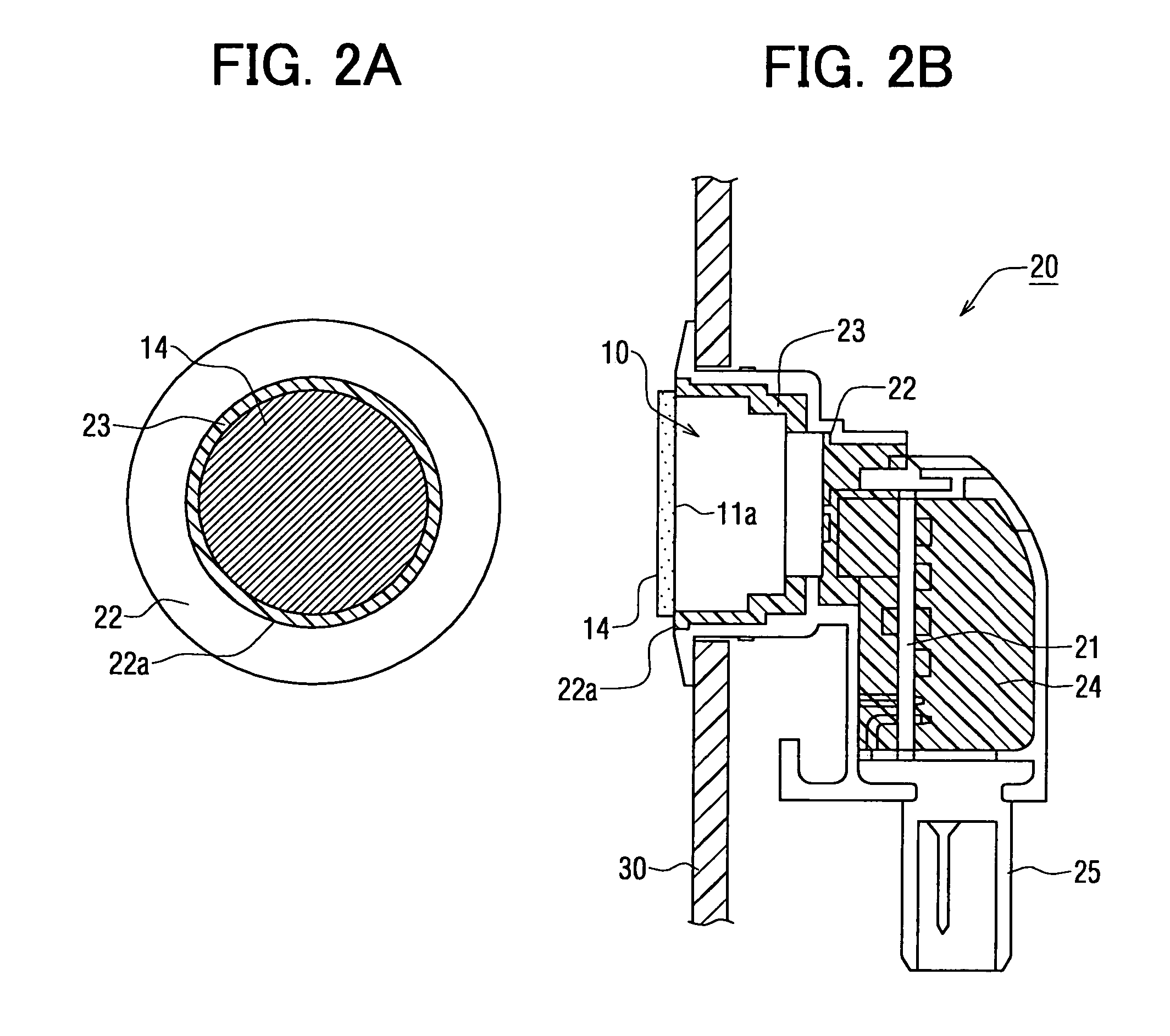
[0013]An ultrasonic transducer 10 of an ultrasonic sensor 20 according to an embodiment of the present invention will be explained below. FIG. 1A shows a front view of the ultrasonic transducer 10; FIG. 1B shows a side view; and FIG. 1C shows a rear view. The transducer 10 is formed of a housing 11 that has an inner space 13 filled with fillers. FIG. 1D shows a sectional side view of the transducer 10 without the fillers.

[0014]The housing 11 is made of aluminum to be electrically conductive. The housing 11 includes a vibrating planar member (or vibrating face) 11a. An outward surface of the vibrating planar member 11a constitutes an outward surface of the housing 11, while an inward surface of the vibrating planar member 11a faces the inner space 13, as shown in FIG. 1D. Inside the housing 11 or within the inner space 13, a piezoelectric element 12 is contained. The piezoelectric element 12 is attached on an inward surface of the vibrating planar member 11a. On the outward surface o...


PUM

PropertyMeasurementUnit
sizeaaaaaaaaaa
coloraaaaaaaaaa
corrosionaaaaaaaaaa

Abstract

An ultrasonic sensor consists of an ultrasonic transducer and a casing. The transducer includes a metal-made housing having an inner space; a vibrating planar member formed in the housing, wherein an outward surface of the vibrating planar member constitutes an outward surface of the housing and an inward surface of the vibrating planar member faces the inner space; and a driving element attached on an inward surface of the vibrating planar member for vibrating the vibrating planar member. This ultrasonic transducer is assembled within the casing and attached to a vehicle via the casing with the outward surface of the vibrating planar member exposed outwardly. Further, a resin film is attached using an adhesive member applied on a rear surface of the film to cover all the outward surface of the vibrating planner member.

Description

CROSS REFERENCE TO RELATED APPLICATIONS[0001]This application is based on and incorporates herein by reference Japanese Patent Application No. 2004-128446 filed on Apr. 23, 2004.FIELD OF THE INVENTION[0002]The present invention relates to an ultrasonic sensor used, for instance, in a vehicular obstacle detection device that is attached to a bumper of a vehicle for detecting an obstacle rearward of or at corners of the vehicle.BACKGROUND OF THE INVENTION[0003]There is proposed, as a conventional technology, an ultrasonic sensor that is attached to a bumper of a vehicle for detecting obstacles around the vehicle. (Refer to Patent Document 1)[0004]Patent Document 1: JP-H04-35600 A[0005]Here, a vibrating planar member (or vibrating face) of this type of the sensor is exposed in its surface outward of the vehicle, so this exposed surface is painted in the same color as the bumper of the vehicle. Further, the ultrasonic sensor is attached to the bumper or regions around the bumper, so thr...

Claims


Application Information

Patent Timeline
Patent Type & Authority Patents(United States)
IPC IPC(8): G01N29/00G01S7/521G01S15/93H04R17/00G10K9/122H01L41/113
CPCG10K9/122H04R1/02H04R17/00H04R2201/02H10N30/88
Inventor NAKAJIMA, AKIRA
Owner DENSO CORP
Why Eureka
Try Eureka