Electromagnetic radiation generation using a laser produced plasma

Inactive Publication Date: 2005-05-12
POWERLASE PHOTONICS
View PDF31 Cites 1 Cited by
  • Summary
  • Abstract
  • Description
  • Claims
  • Application Information

AI Technical Summary

Benefits of technology

[0023] Reducing nozzle erosion reduces the likelihood of debris reaching the optical elements and contaminating them.
[0024] It will be appreciated that while the beveled outer rim portion need only be provided upon the side of the nozzle from which the laser light is incident, the manufacturing of the nozzle may be simplified and the advantages of increased erosion resistance extended if the beveled outer rim extends around the complete nozzle.
[0025] It will be appreciated that the outer wall of the nozzle could have many different cross sections. As an example, the outer wall of the nozzle could have a square cross section with one edge of the outer rim being beveled to avoid interfering with the incident laser light. However, in preferred embodiments of the invention the outer wall of the nozzle has a circular cross section as this generally eases manufacturing and provides the required strength to the nozzle while not providing a nozzle that is too big as a subject for plasma erosion and contamination generation.
[0026] While the beveled outer rim portion can have various different profiles providing they avoid interfer

Problems solved by technology

It is normally regarded that continuous flow would not be practical due to the high pumping requireme

Method used


Image

  • Electromagnetic radiation generation using a laser produced plasma
  • Electromagnetic radiation generation using a laser produced plasma
  • Electromagnetic radiation generation using a laser produced plasma

Examples


Embodiment Construction

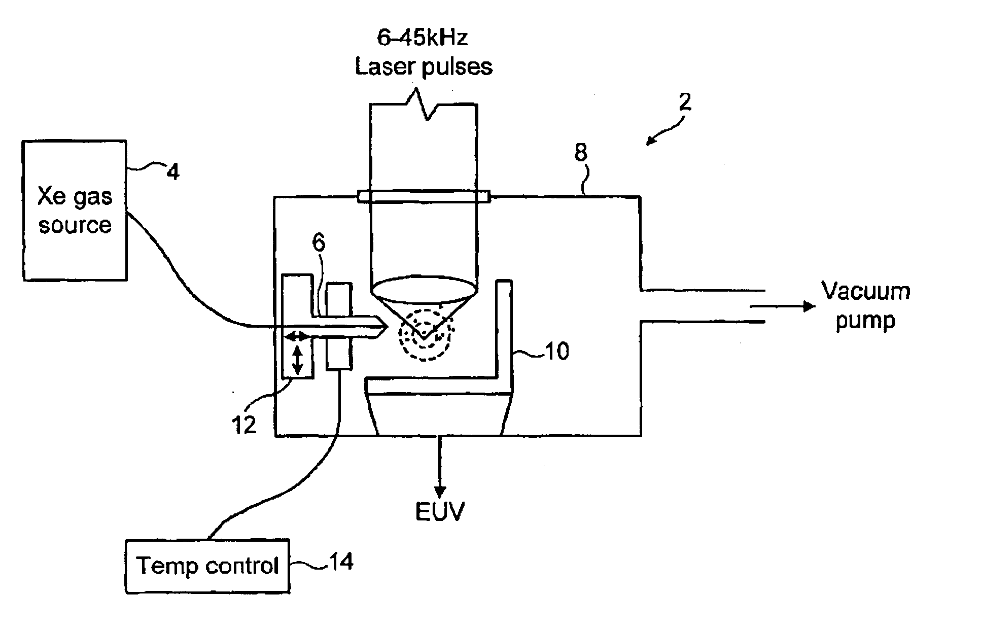
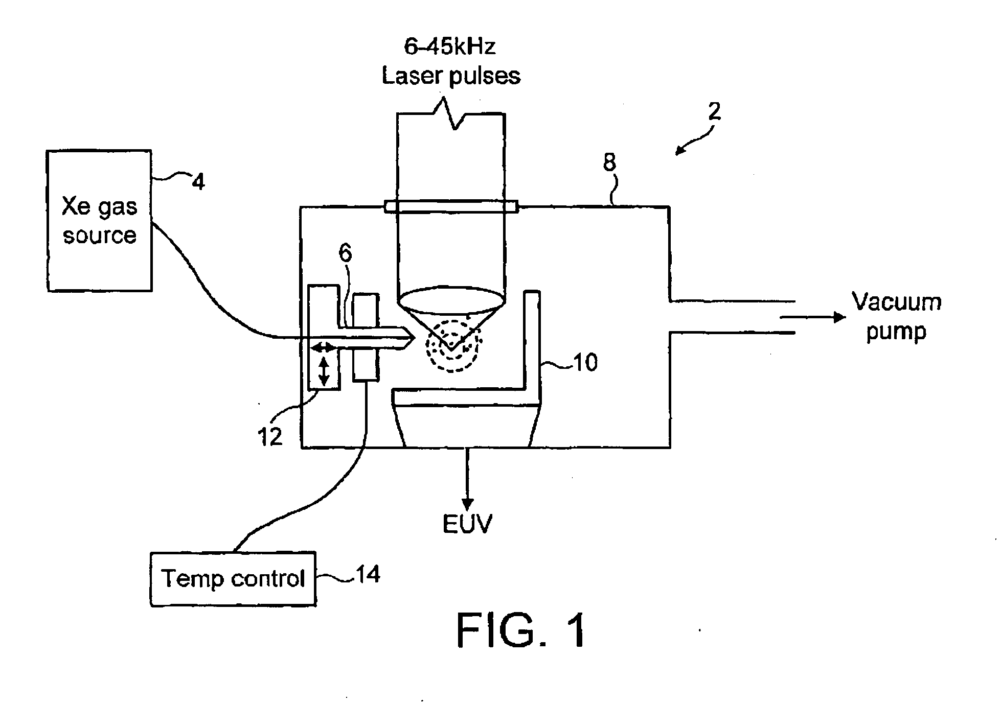
[0037]FIG. 1 shows an apparatus 2 for generating extreme ultraviolet light. This apparatus 2 operates by directing a flow of high pressure Xenon gas (for example at a pressure of 10 to 70 bar) from a Xenon gas source 4 through a nozzle 6 and into the interior of a low pressure chamber 8. As the Xenon gas emerges from the nozzle 6 it is cooled to an extent whereby matter suitable for use as a target for generating a plasma is formed. This matter may be in the form of clusters of Xenon atoms. A high power stream of high repetition rate laser pulses from a single or multiplexed lasers is focused onto the Xenon atom clusters. The repetition rate is preferably between 1 kHz and 100 kHz, more preferably between 2 kHz and 20 kHz and achieved in single or multiplex configuration. This heats the Xenon atom clusters to a degree where a plasma forms, this plasma then emitting extreme ultraviolet radiation. Collection optics 10 serve to gather this extreme ultraviolet radiation for use within o...


PUM


Abstract

An extreme ultraviolet radiation generator is disclosed in which Xenon gas is continuously ejected from a high pressure nozzle into a low pressure chamber to generate Xenon atom clusters which are irradiated with a high repetition rate pulsed laser to form a plasma and yield quasi-continuous EUV generation. The nozzle has a beveled outer rim to enable the focus point of the laser light to be brought close to the nozzle. The nozzle is cooled to a temperature at which background Xenon gas condenses onto the nozzle forming a protective layer. A gas compressor serves to recirculate the Xenon gas and batch purification triggered by a mass spectrometer monitoring gas purity may be periodically applied.

Description

CROSS-REFERENCE TO RELATED APPLICATIONS [0001] This application claims priority of International Application Number PCT / GB01 / 03871, which was filed on Aug. 30, 2001, and published as International Publication Number WO 02 / 19781 A1 on Mar. 7, 2002 (the “'871 application”), and which in turn claims priority from Great Britain Patent Application Number 0021455.1, filed on Aug. 31, 2000 (the “'455 application”), from Great Britain Patent Application Number 0021458.5, filed on Aug. 31, 2000 (the “'458 application”), and from Great Britain Patent Application Number 0021459.3, filed on Aug. 31, 2000 (the “'459 application”). The '871 application, the '455 application, the '458 application, and the '459 application are all hereby incorporated herein by reference.BACKGROUND OF THE INVENTION [0002] Field of the Invention [0003] The present invention relates generally to the field of the production of electromagnetic radiation from a laser produced plasma, and more particularly to the generati...

Claims


Application Information

Patent Timeline
IPC IPC(8): G21K5/00G03F7/20G21K5/02G21K5/08H01L21/027H05G2/00H05H1/24
CPCH05G2/003H05G2/006H05G2/008
Inventor TAYLOR, ALAN G.KLUG, DAVID R.MERCER, IAN P.ALLWOOD, DANIEL A.
Owner POWERLASE PHOTONICS
Why Eureka
Try Eureka