Sliding member

a sliding member and a technology of sliding layer, applied in the direction of shaft and bearing, rotary bearing, engine components, etc., can solve the problems of a crack that extends substantially circumferentially on the surface of the sliding layer, and the shear failure is more likely to occur at the interface between the back-metal layer and the crack

Active Publication Date: 2022-09-13
DAIDO METAL CO LTD
View PDF8 Cites 0 Cited by
  • Summary
  • Abstract
  • Description
  • Claims
  • Application Information

AI Technical Summary

Benefits of technology

[0008]Thus, an object of the present invention is to overcome the disadvantages of the conventional technique and provide a sliding member that is less likely to be subjected to damage such as a crack on a surface of a sliding layer and shear failure between the sliding layer and a back-metal layer, during the operation of a bearing device

Problems solved by technology

It was found that, in this case, if the resin composition of the sliding layer is thermally expanded, due to frictional heat generated by sliding, in an almost isotropic manner in an in-plane direction of the sliding surface, damage such as a crack that extends in a substantially circumferential direction is highly likely to occur on the surface of the sliding layer, when the resin composition is elastically deformed due to the pressure of the fluid film.
Furthermore, another problem has been found that, when an amount of thermal expansion of the resin composition of the sliding layer is approximately same between the in-plane direction of the sliding surface and a direction perpendicular to the sliding surface (thickness direction), shear failure is more likely to occur at an interface between the back-metal layer made of metal and the sliding layer.

Method used


Image

  • Sliding member
  • Sliding member
  • Sliding member

Examples


examples

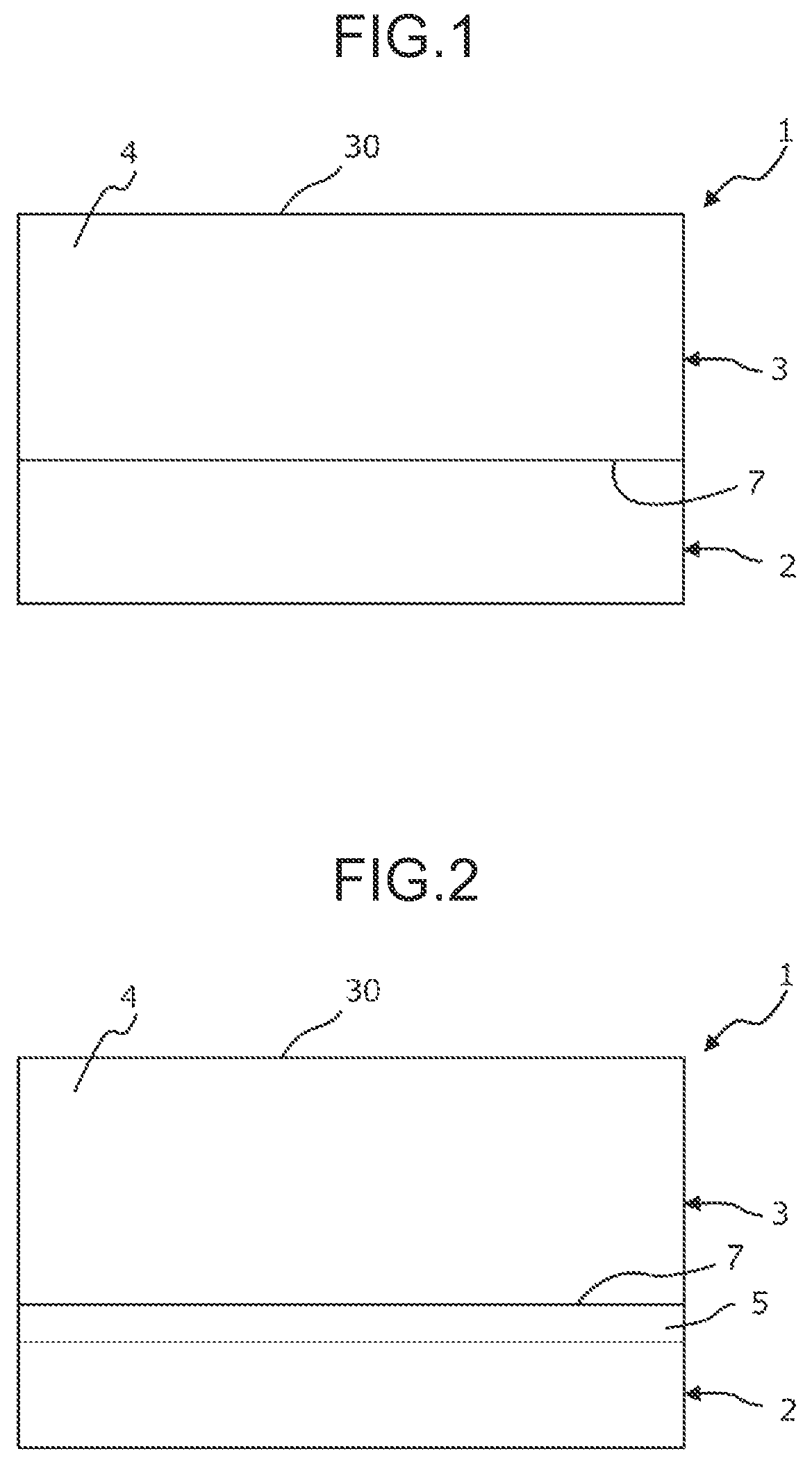
[0071]Examples 1 to 6 of the sliding member including the back-metal layer and the sliding layer according to the present invention and Comparative Examples 11 to 14 were produced in the following manner. Table 2 shows composition of the sliding layer of the sliding members of Examples and Comparative Examples.

[0072]

TABLE 2Sliding test resultsCondition 1Condition 2Linear expansionPres-PresencePres-PresenceComposition (volume %)CoefficientKT / enceof shearenceof shearCeramicCarbonGraph-(×10−5 / ° C.)((KS +offailure atoffailure atSamplePEEKPEKfibersfibersitePTFECaF2KSKJKTKS / KJKJ) / 2)cracksinterfacecracksinterfaceEx-11006.83.66.81.91.3NotNotPresentNotamplespresentpresentpresent21004.93.37.91.51.9NotNotNotNotpresentpresentpresentpresent31003.63.28.61.12.5NotNotNotNotpresentpresentpresentpresent410053.67.71.41.8NotNotNotNotpresentpresentpresentpresent5782024.62.86.31.61.7NotNotNotNotpresentpresentpresentpresent67815524.32.96.41.51.8NotNotNotNotpresentpresentpresentpresentCom-111007.73.76.32.1...


PUM

PropertyMeasurementUnit
volume %aaaaaaaaaa
volume %aaaaaaaaaa
center angleaaaaaaaaaa

Abstract

Provided is a sliding member for a thrust bearing. The sliding member includes a back-metal layer and a sliding layer, and has a partially annular shape. The sliding layer includes a synthetic resin and has a sliding surface. In a center line region of the sliding layer, the sliding layer has a linear expansion coefficient KS in a direction parallel to a circumferential direction of the sliding member, a linear expansion coefficient KJ in a direction parallel to a radial direction of the sliding member, and a linear expansion coefficient KT in a direction perpendicular to the sliding surface, and the linear expansion coefficients KS, KJ, and KT satisfy the following relations (1) and (2): Relation (1): 1.1≤KS / KJ≤2; and Relation (2): 1.3≤KT / {(KS+KJ) / 2}≤2.5.

Description

TECHNICAL FIELD[0001]The present invention relates to a sliding member for a thrust bearing, and specifically relates to a sliding member that has a partially annular shape and includes a back-metal layer and a sliding layer including a synthetic resin composition. The present invention also relates to a thrust bearing including the sliding member.RELATED ART[0002]A thrust bearing has been used as a thrust bearing for a rotating shaft of an exhaust turbine, a large-sized power generator or the like. Such thrust bearing is configured that a plurality of bearing-pad-shaped sliding members having a partially annular shape are arranged in a circumferential direction to face a thrust collar surface of the rotating shaft. In such a tilting pad thrust bearing, the sliding members having a partially annular shape are supported so that the sliding members can slightly swing by a pivot with respect to the thrust collar surface of the shaft member. During steady operation of the exhaust turbin...

Claims


Application Information

Patent Timeline
Patent Type & Authority Patents(United States)
IPC IPC(8): F16C17/06F16C33/20F16C31/02C08K3/04C08K3/16C08K3/34C08K7/06C08K7/10C08L61/16
CPCF16C31/02C08K3/04C08K3/16C08K3/34C08K7/06C08K7/10C08L61/16F16C17/06F16C33/20F16C33/201C08K2003/162F16C2202/22F16C2208/02F16C2208/04F16C2208/36F16C2208/40F16C2208/42F16C2208/44F16C2208/52F16C2208/60F16C2208/78F16C2208/82F16C2208/86F16C2208/90F16C33/205F16C33/208F16C17/243F16C17/04F16N15/02F16C2202/10F16C2208/22F16C2208/66F16C2208/58F16C2208/62F16C2208/32F16C2206/40F16C2202/52F16C2202/54F16C2204/10F16C2204/60F16N2210/14F16C33/206
Inventor NAKAJIMA, HIDEYUKI
Owner DAIDO METAL CO LTD
Why Eureka
Try Eureka