Heat exchanger
a heat exchanger and heat exchanger technology, applied in the field of fluid cooling pipes, can solve the problems of difficult placement of the body to the underfloor or the back surface of the apparatus, time-consuming, and bulky body, and achieve the effects of improving durability, easy manufacturing of products, and easy manufacturing
- Summary
- Abstract
- Description
- Claims
- Application Information
AI Technical Summary
Benefits of technology
Problems solved by technology
Method used
Image
Examples
first embodiment
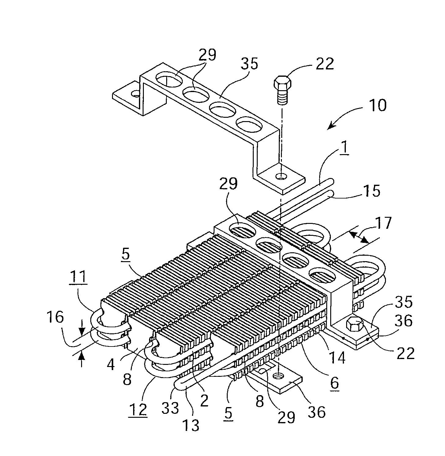
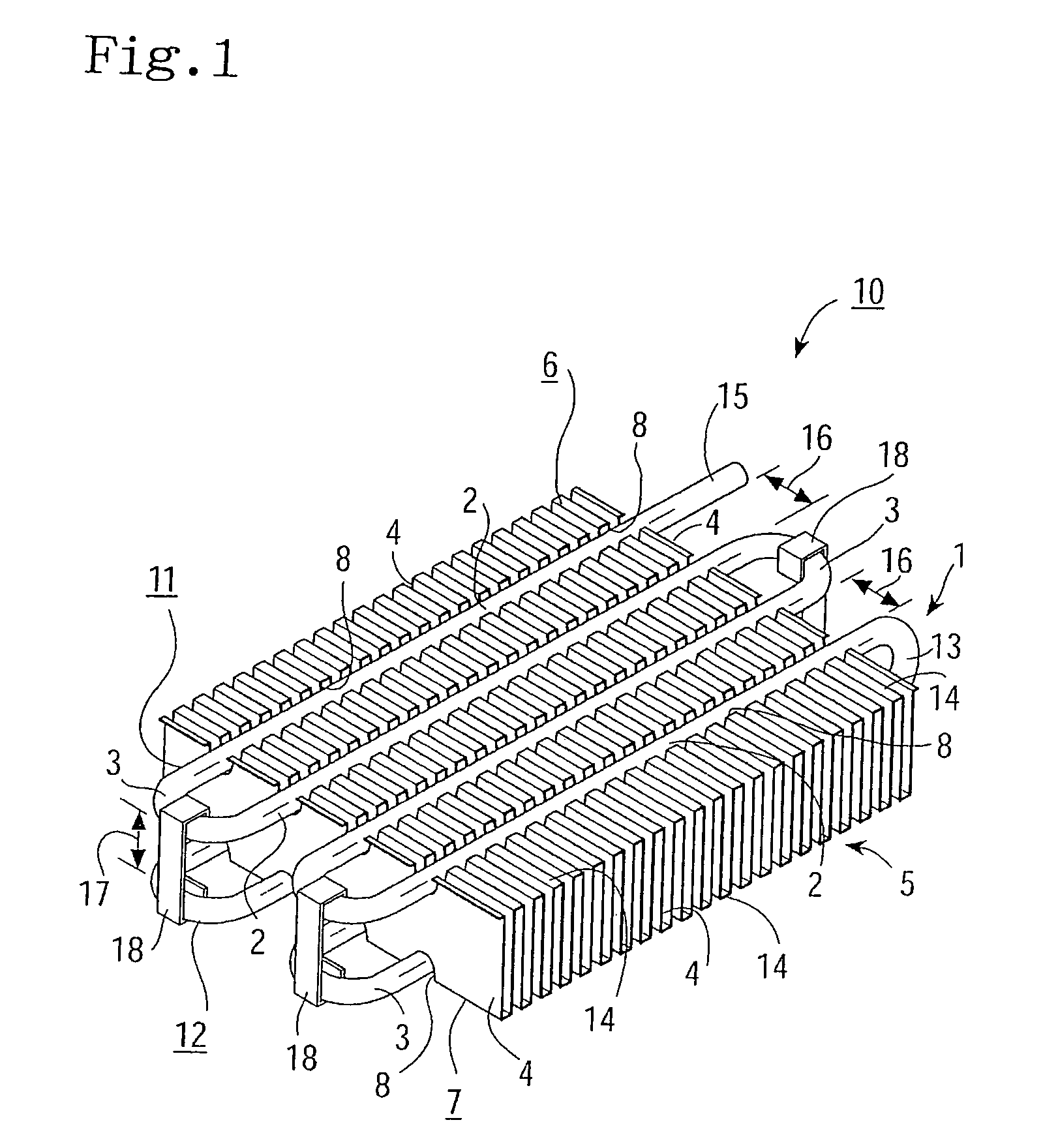
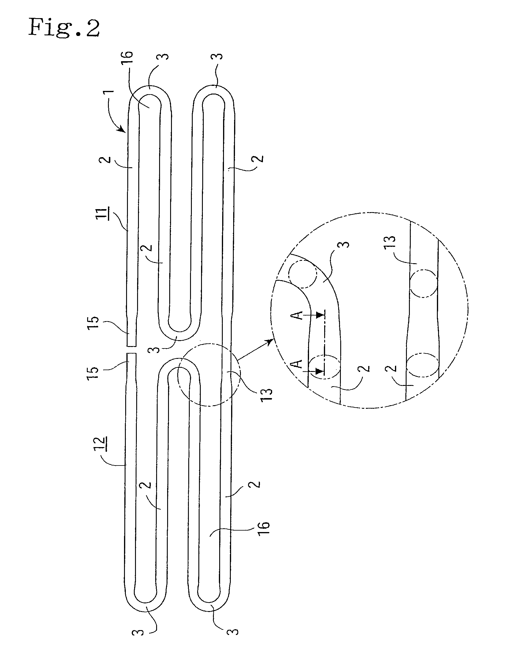
[0068]The first embodiment in which the heat exchanger according to the present invention is exemplified as a fuel pipe to be disposed onto an underfloor of vehicles is hereinafter explained into detail referring to FIGS. 1 to 6. (1) denotes a meandering pipe main body in which a pair of meandering sections (11), (12), composed of a plurality of straight pipe sections (2) arranged in parallel with desired opposing gaps (16) between the straight pipe sections (2) and bend portions (3) for connecting the plurality of straight pipe sections (2), are placed within insertion gap (17) for a fin member so as to be opposed to each other. Within insertion gap (17) formed between the first meandering section (11) and the second meandering section (12), there is placed fin member (5) provided with a plurality of rectangular shaped engagement grooves (8) at constant distances on both end surfaces (6), (7) opposing to each other and composed of a plurality of fins (4) in parallel. Further, strai...
third embodiment
[0088]In such conventional art as taught in Japanese Patent Laying-Open No. 2003-88924 that a mandrel is employed as the expanding means, it is necessary to connect a U-bend pipe to the straight pipe after the straight pipe having been inserted into thin fins, is expanded. To the contrary, in the present invention, meandering pipe main body (1) is inwardly pressurized to expand after disposing straight pipe sections (2) in engagement grooves (8), thereby fitting straight pipe sections (2) with engagement grooves (8) tightly. Therefore, brazing or welding or the like between pipes after the expansion thereof can be omitted, and thus the working efficiency can be improved and the brakeage of fin member (5) or other inadvertent damages are avoidable.
[0089]Straight pipe sections (2) are secured with engagement grooves (8), according to the first and second embodiments, by clipping means such as clips (18) and according to the third embodiment, by expansion of straight pipe sections (2)....
fifth embodiment
[0093]In the conventional art as taught in Japanese Patent Laying-Open No. 2003-88924, the thin fins are arranged in parallel, whereas in the present invention, both ends of fins (4) are cut off to preliminary form engagement grooves (8), the plurality of such fins are arranged in parallel to form fin member (5), and then straight pipe sections (2) are fitted in thus formed engagement grooves (8). Such construction, comparing to the conventional art in which throughholes are provided in fins to insert the pipe main body therein, is easy to process, avoidable of deformation or damage of fins (4) upon the disposing operation of straight pipe sections (2), and thus the working efficiency can be improved. Fin member (5) is clipped with the pair of the meandering sections (11), (12) so that stability of each fin (4) can be enhanced and better permanence of heat exchanger (10) is obtainable.
[0094]When heat exchanger (10) as described in the fifth embodiment is utilized as a fuel pipe, the...
PUM
 Abstract
Description
Claims
Application Information
 - R&D
- Intellectual Property
- Life Sciences
- Materials
- Tech Scout
- Unparalleled Data Quality
- Higher Quality Content
- 60% Fewer Hallucinations
Browse by: Latest US Patents, China's latest patents, Technical Efficacy Thesaurus, Application Domain, Technology Topic, Popular Technical Reports.
© 2025 PatSnap. All rights reserved.Legal|Privacy policy|Modern Slavery Act Transparency Statement|Sitemap|About US| Contact US: help@patsnap.com


