
Method and system for maximum residency replacement of cache memory

a cache memory and maximum residency technology, applied in the field of digital signal processing, can solve the problems of high cost of updating in terms of operational resource use and energy consumption, repetitive algorithms, and inability to meet the requirements of fast math in digital signal processing, so as to avoid incoherence

Inactive Publication Date: 2009-09-01
QUALCOMM INC
View PDF3 Cites 2 Cited by
  • Summary
  • Abstract
  • Description
  • Claims
  • Application Information

AI Technical Summary

Benefits of technology

This patent describes a technique for replacing cache memory in a digital signal processor to improve its operation and processing speed. The technique involves creating a FIFO cache way listing of victim ways that result in tag miss allocations. The method and system prevent the placement of a victim way on the FIFO cache way listing if it has not been previously allocated and avoids reuse hazards. The process continues until a usable cache way is selected. Overall, this technique allows for more efficient processing and faster software applications for electronic devices.

Problems solved by technology

Digital signal processing requires fast math in complex, but repetitive algorithms.
This updating is expensive in terms of operational resource use and energy consumption.
The costs of forwarding the storage bit information from pipeline to pipeline can be excessive, particularly when there is a limited time budget for each pipeline stage.
That is, the handling of the storage bit information from one pipeline stage to another may exact an undesirable cost during the multi-threaded operation.
Because the large busses that convey the storage bit information consume power and introduce performance delays, there is the need to reduce or eliminate the conveyance of such storage bit information in a cache way replacement policy.
In addition, the present embodiment skips such ways on the FIFO cache way listing which present a reuse hazard.

Method used


Image

  • Method and system for maximum residency replacement of cache memory
  • Method and system for maximum residency replacement of cache memory
  • Method and system for maximum residency replacement of cache memory

Examples


Embodiment Construction

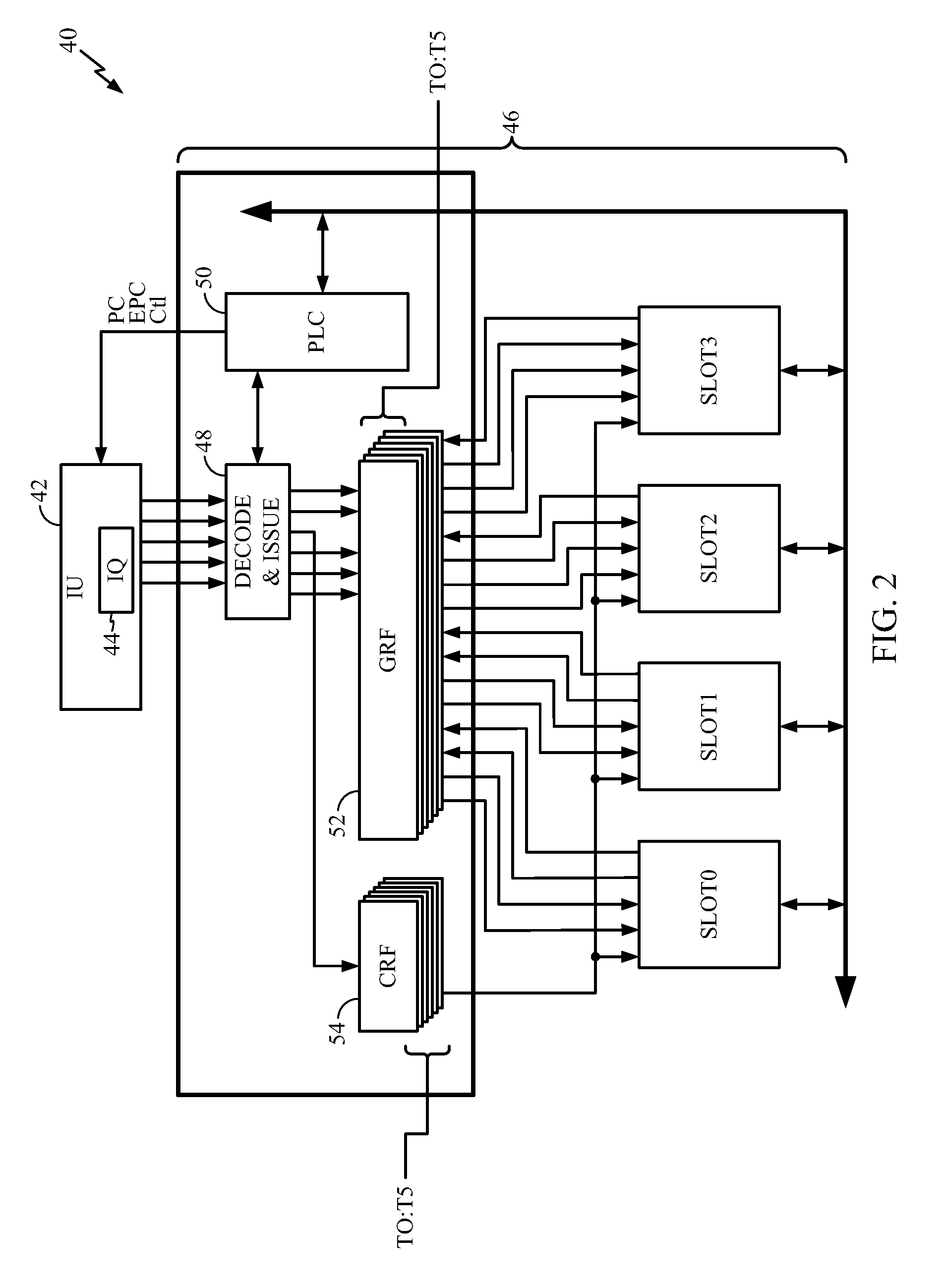
[0028]The disclosed subject matter of a method and system for maximum residency replacement of cache memory as here presented has use in a very wide variety of digital signal processing applications, including those involving multi-threaded processing. One such application appears in telecommunications and, in particular, in wireless handsets that employ one or more DSP circuits. Consequently, the following FIGUREs describe a telecommunications DSP within which one may use the present teachings. Remember, however, that the implementation here described provides but one of a virtually limitless set of applications to which the disclosed subject matter may apply.

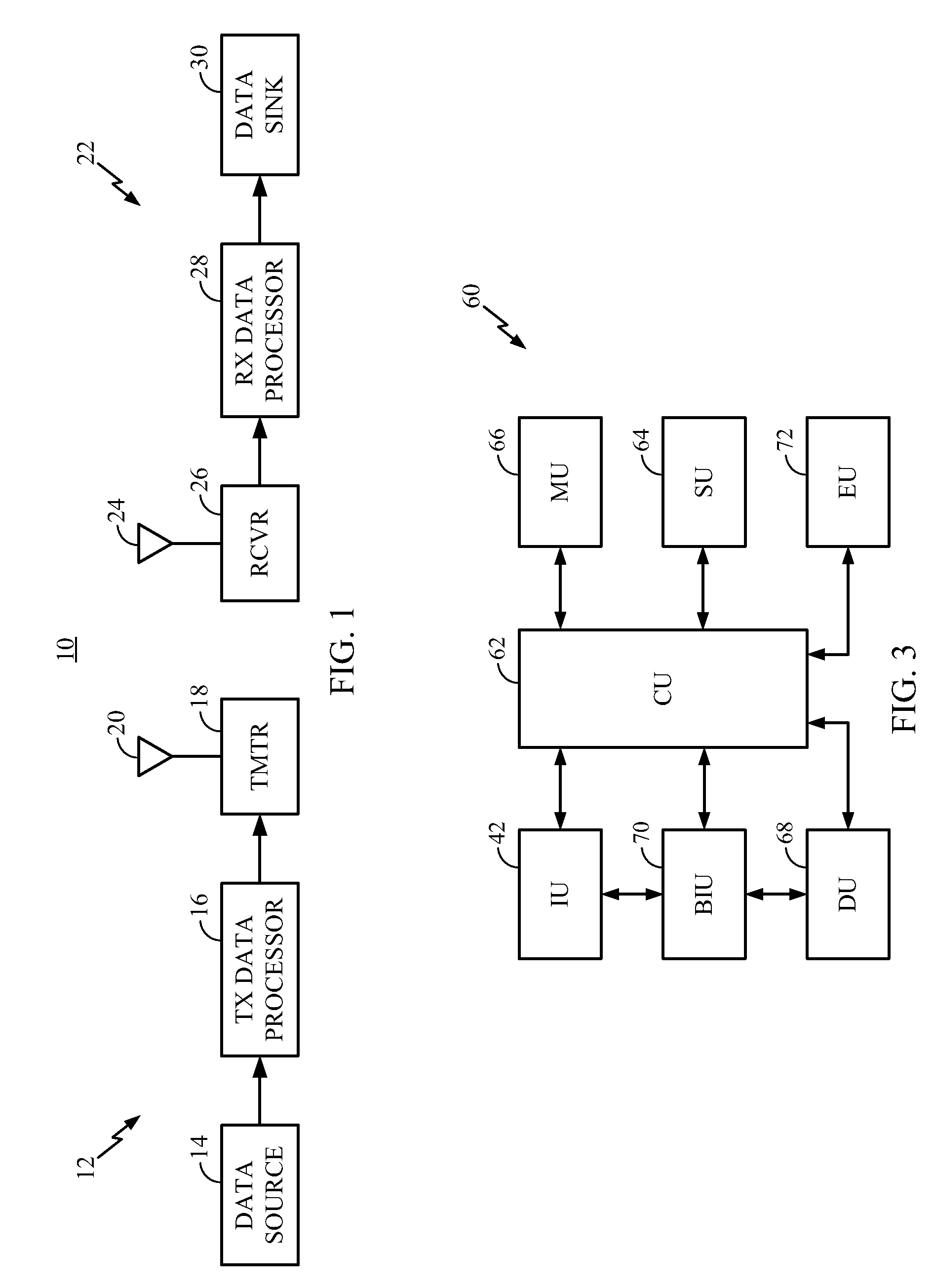
[0029]For the purpose of explaining how such a wireless handset may be used, FIG. 1 provides a simplified block diagram of communications system 10 that may implement the presented embodiments of the disclosed data processing method and system. At transmitter unit 12, data is sent, typically in blocks, from data source 14 to t...


PUM


Abstract

Techniques for use in CDMA-based products and services, including replacing cache memory allocation so as to maximize residency of a plurality of set ways following a tag miss allocation. Herein, steps and instructions provide for forming a first-in, first-out (FIFO) cache way listing of victim ways for the cache memory, wherein the depth of the FIFO cache way listing approximately equals the number of ways in the cache memory. The method and system place a victim way on the FIFO cache way listing only in the event that a tag miss results in a tag miss allocation, the victim way is placed at the tail of the FIFO cache way listing after any previously selected victim way. Use of a victim way on the FIFO cache way listing is prevented in the event of an incomplete prior allocation of the victim way by, for example, stalling a reuse request until such initial allocation of the victim way completes or replaying a reuse request until such initial allocation of the victim way completes.

Description

[0001]This application is a continuation of Utility application Ser. No. 11 / 437,501 entitled “METHOD ANS SYSTEM FOR MAXIMUM RESIDENCY REPLACEMENT OF CACHE MEMORY” and filed on May 17, 2006.FIELD[0002]The disclosed subject matter relates to digital signal processing in support of communications products and services. More particularly, this disclosure relates to a novel and improved method and system for maximum residency replacement of cache memory as may find use in a digital signal processor for a handset or other communications system.DESCRIPTION OF THE RELATED ART[0003]Increasingly, electronic equipment and supporting software applications involve digital signal processing. For example, home theatre, computer graphics, medical imaging and telecommunications applications generally rely on digital signal processing technology. Digital signal processing requires fast math in complex, but repetitive algorithms. Many such applications require computations in real-time, i.e., the sign...

Claims


Application Information

Patent Timeline
Patent Type & Authority Patents(United States)
IPC IPC(8): G06F12/12
CPCG06F12/123G06F12/128G06F12/126G06F12/0859Y02B60/1225Y02D10/00G06F12/08G06F12/12G11C8/04
Inventor AHMED, MUHAMMAD
Owner QUALCOMM INC
Learn More