
Eureka
For R&D, Eureka makes reading and utilizing patents & technical documents easy.
Eureka AIR
Designed for self-driven R&D workflows. Generate viable solutions, solve complex R&D challenges, empower your innovation with AI.

Eureka Materials
Designed for material experts only. Revolutionize your material R&D, from search, analyze, to developing new materials.

TechResearch
Generate reliable direction feasibility study reports for your R&D in just a few steps.

TechSeek
Discover and master advanced knowledge NOW. Basics, ideas, possibilities, all at once.

TechMind
As an expert in R&D Theories, TechMind can generates customized viable solutions instantly.

TechRisk
Analyze your overall solution with one click, know your potential R&D risks in advance.

TechMonitor
Get weekly tech updates, stay abreast of the latest tech innovations and key insights.
Metal spinning method and apparatus
- Summary
- Abstract
- Description
- Claims
- Application Information
AI Technical Summary
Benefits of technology
Problems solved by technology
Method used
Image

Examples
embodiment 1
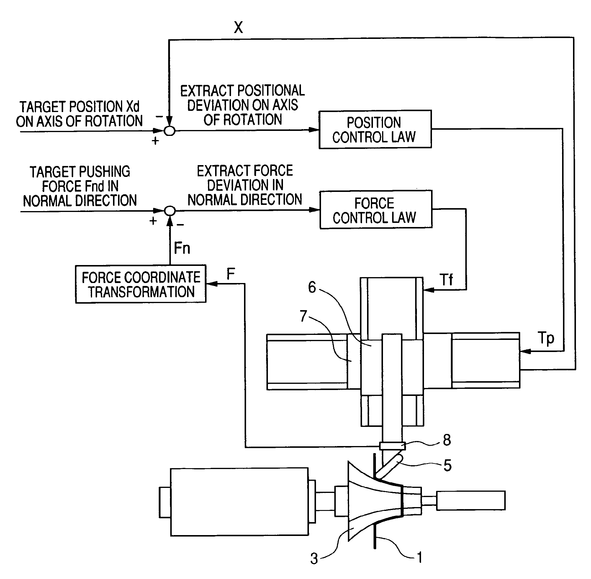
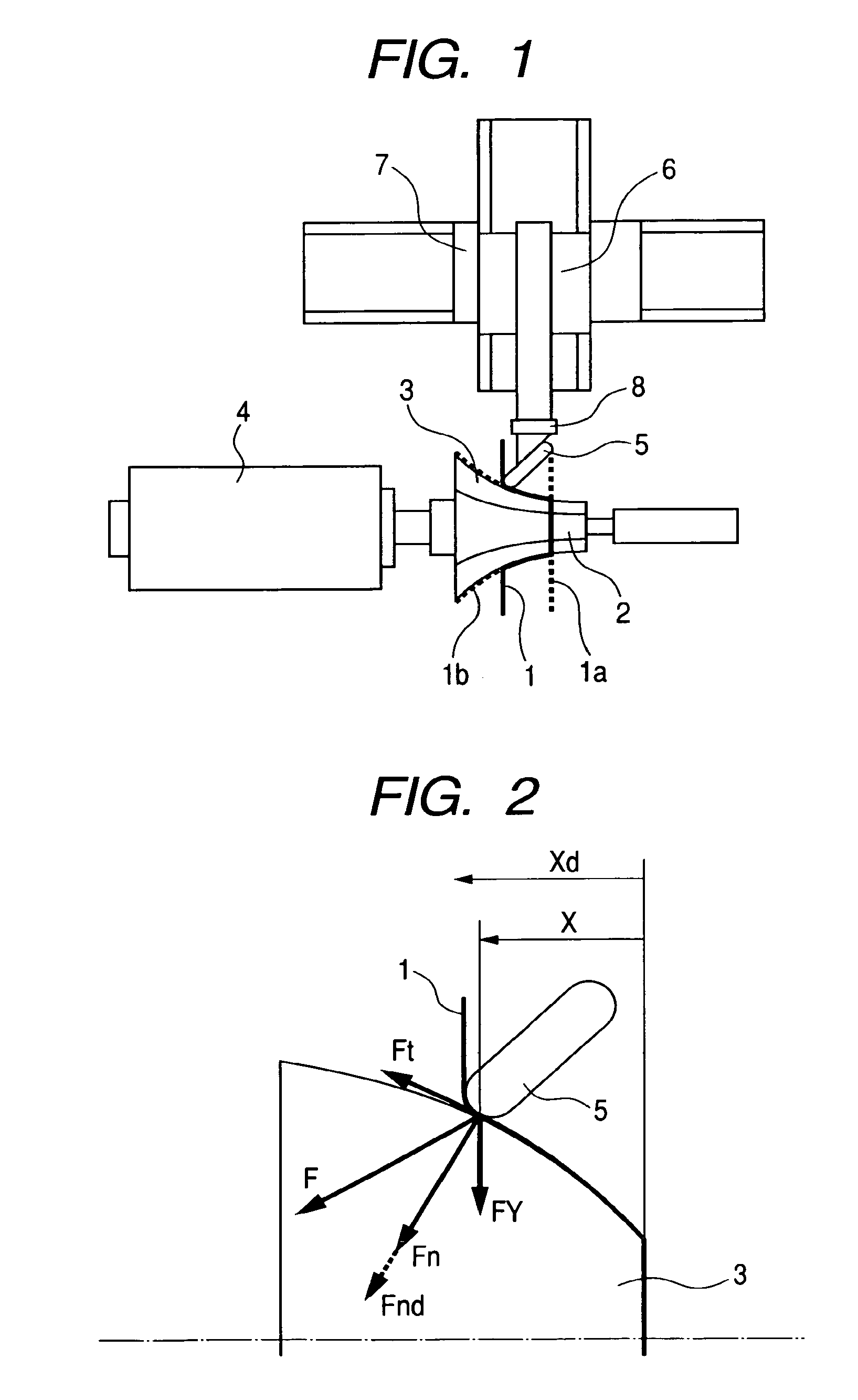
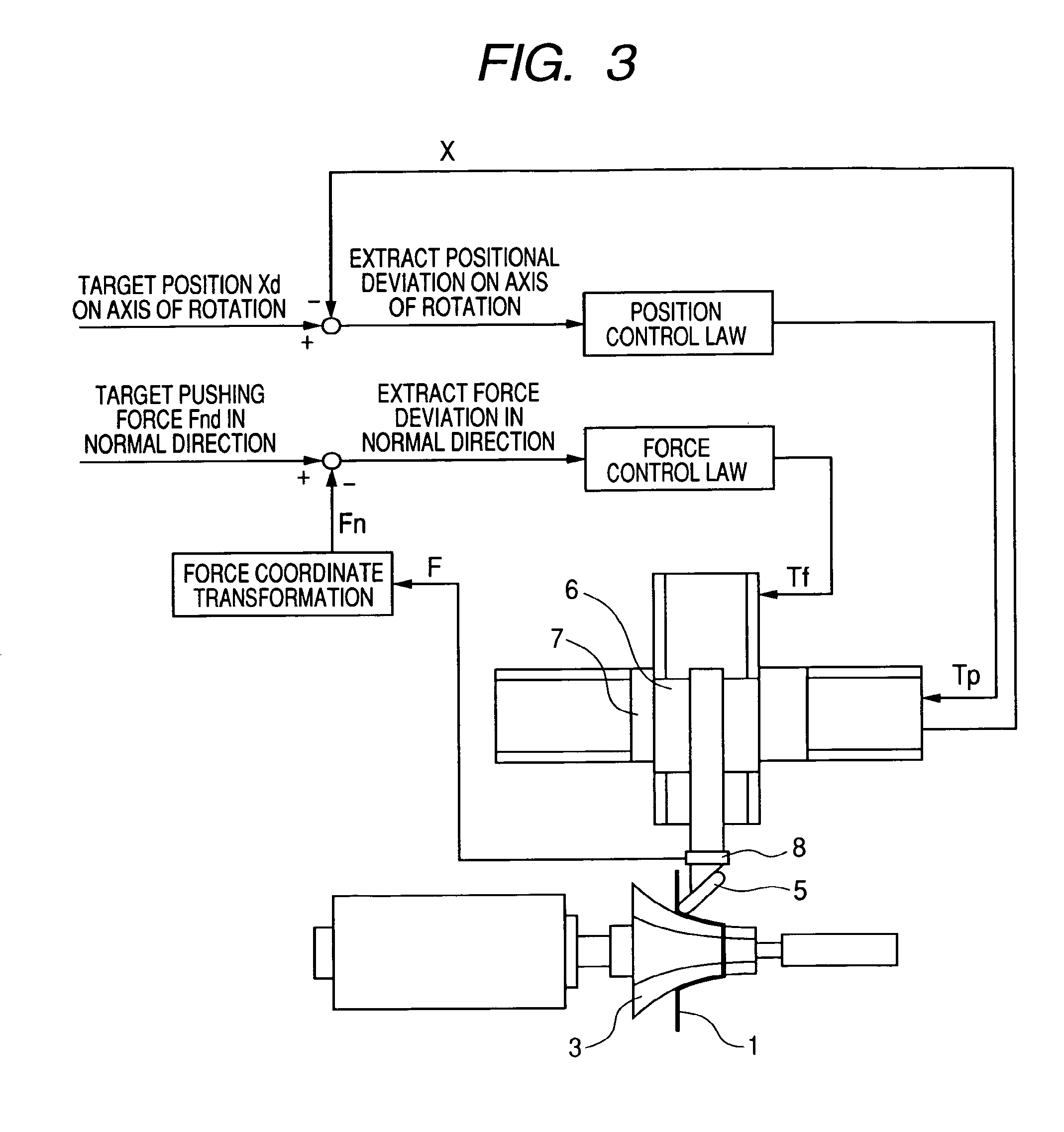
[0022]In the following, FIG. 1 is a schematic diagram of an embodiment of an apparatus for performing a metal spinning method of the invention.
[0023]The invention is provided with a forming roller 5 and actuators for driving the forming roller 5 to move longitudinally and transversely. A jig 2 is shaped to merge into the front surface of a mandrel 3, and a work 1 is fixedly clamped between the jig 2 and the mandrel so that it is rotated together with the mandrel 3 by a spindle motor 4. This spindle motor 4 is equipped with an angle sensor such as an encoder for detecting the angle of rotation.
[0024]The forming roller 5 is moved back and forth in the radial direction of the mandrel 3 by a linear motion table 6 driven by the (not-shown) actuator such as a ball screw or a hydraulic cylinder. On the other hand, the linear motion table 6 is moved back and forth in the direction of the axis of rotation of the mandrel 3 by a linear motion table 7. Each of these linear motion tables 6 and 7...
experimental examples
[0039]Experiments were made for verifying the spinning method and apparatus according to the invention, as described in the following. An experimental apparatus used in the experiments is shown in FIG. 6. The experimental apparatus had basically the same constitution as that shown in Embodiment 1, and a forming roller 20 was enabled to move in directions of an X axis and a Y axis by individual motors 21 and 22. The conditions for setting the angle or the like of the forming roller 20 with respect to the mandrel 23 are described in the following.
[0040]For these linear feeds on the X axis and the Y axis, the ball screws were individually driven by the servo motors 21 and 22. The mandrel 23 (on θ-axis) was rotated by a servo motor 24 with a reduction gear. The θ-axis was slanted by 60 degrees with respect to the X axis.
[0041]The forming roller 20 had a diameter of 70 mm and a roundness of edge of 9.5 mm. A force sensor 25 was interposed between the forming roller 20 and the Y axis.
[004...
PUM
 Abstract
Description
Claims
Application Information
 - R&D Engineer
- R&D Manager
- IP Professional
- Industry Leading Data Capabilities
- Powerful AI technology
- Patent DNA Extraction
Browse by: Latest US Patents, China's latest patents, Technical Efficacy Thesaurus, Application Domain, Technology Topic, Popular Technical Reports.
© 2024 PatSnap. All rights reserved.Legal|Privacy policy|Modern Slavery Act Transparency Statement|Sitemap|About US| Contact US: help@patsnap.com