System for monitoring temperature and pressure during a molding process

a technology of temperature and pressure monitoring and molding process, which is applied in the direction of auxillary shaping apparatus, manufacturing tools, food shaping, etc., can solve the problems of increasing the variance of properties from one color to another, unable to avoid the properties of plastic materials, and difficult to maintain material properties constant from batch to batch, so as to eliminate waste of time and energy and optimize the performance of one or more aspects.

a technology of temperature and pressure monitoring and molding process, which is applied in the direction of auxillary shaping apparatus, manufacturing tools, food shaping, etc., can solve the problems of increasing the variance of properties from one color to another, unable to avoid the properties of plastic materials, and difficult to maintain material properties constant from batch to batch, so as to eliminate waste of time and energy and optimize the performance of one or more aspects.

US7585166B2Inactive Publication Date: 2009-09-08BUJA FREDERICK J

Image

  • System for monitoring temperature and pressure during a molding process
  • System for monitoring temperature and pressure during a molding process
  • System for monitoring temperature and pressure during a molding process

Examples


Embodiment Construction

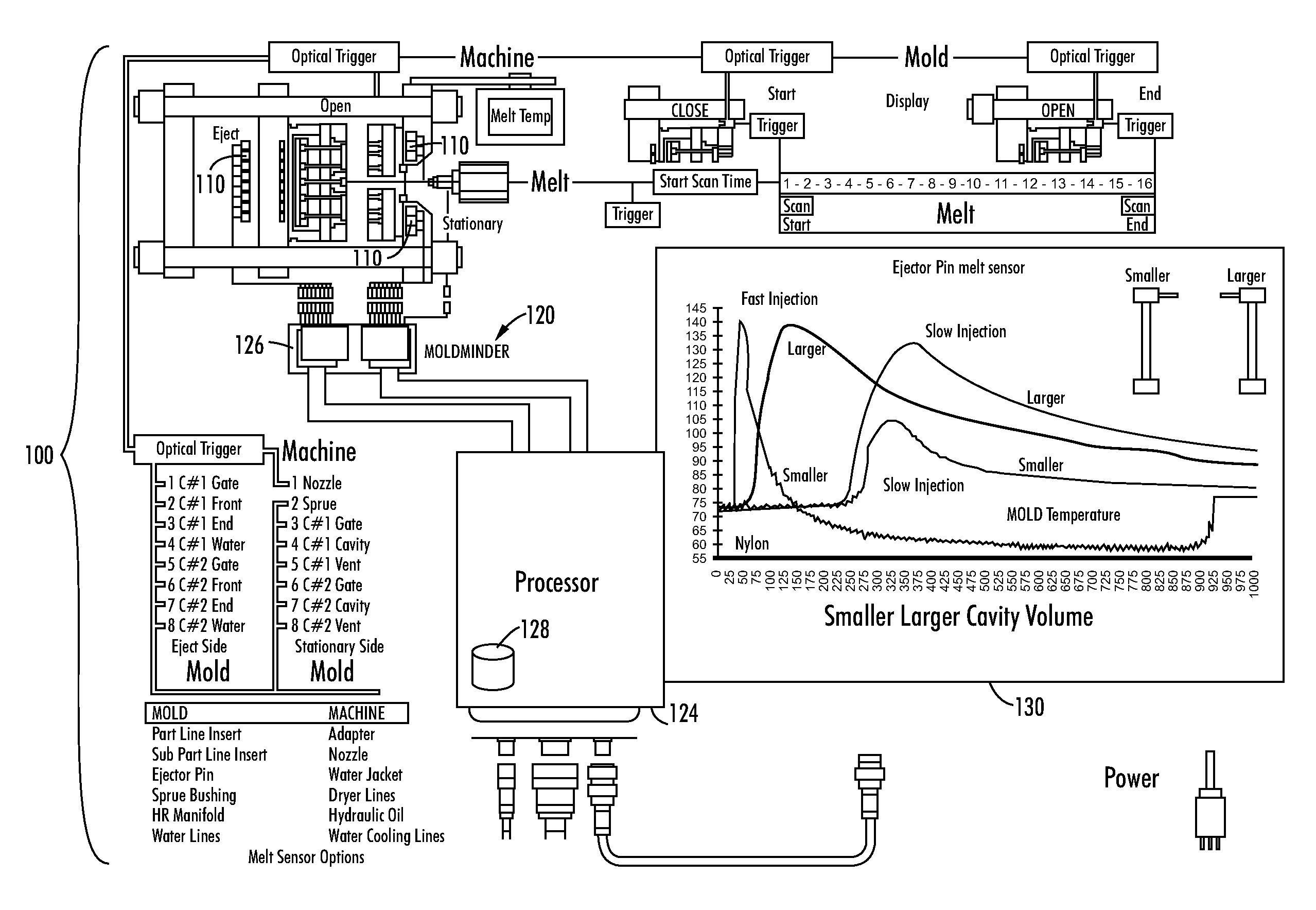
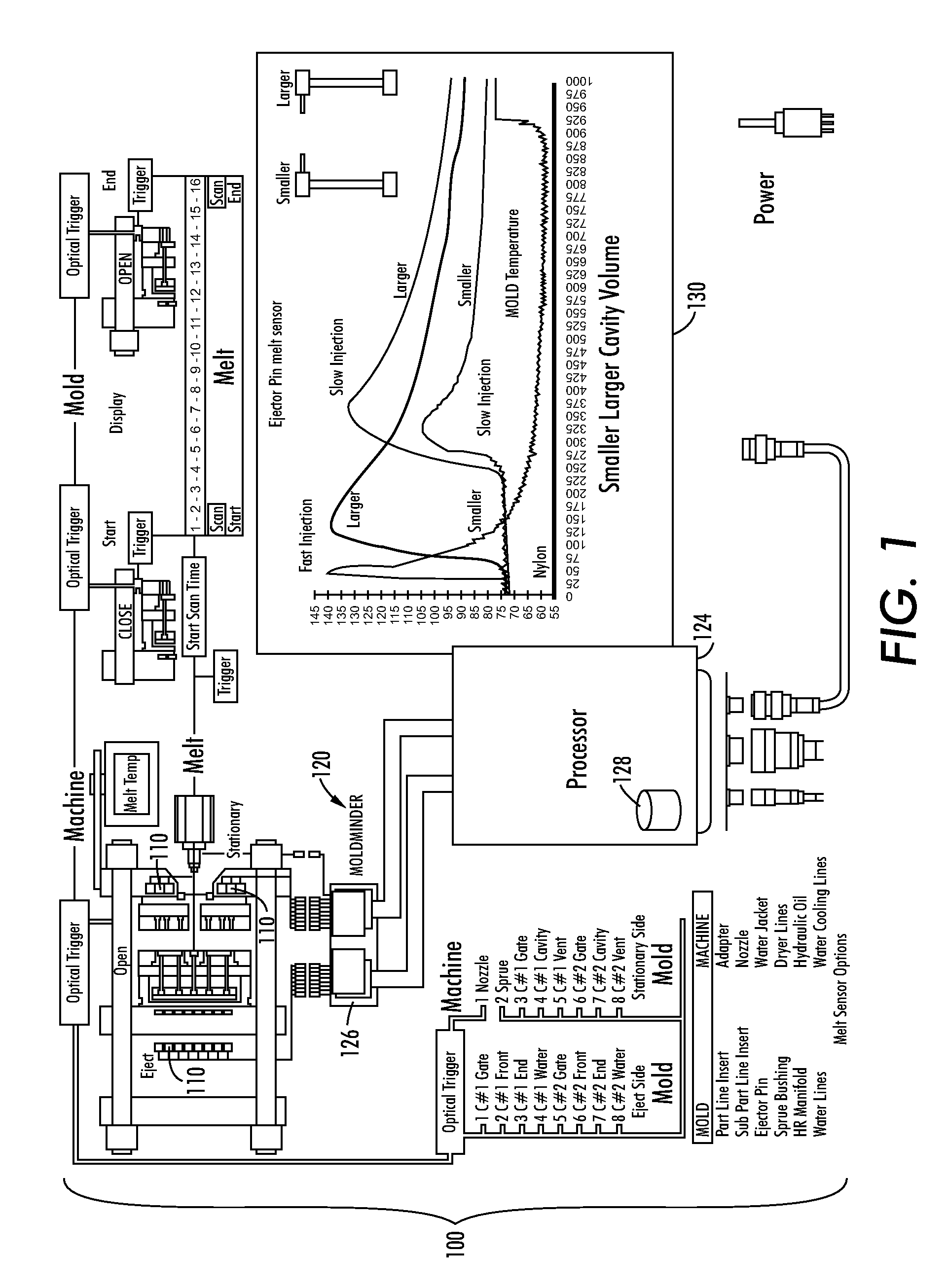
[0033]As more particularly set forth below, the disclosed system and methods are directed to the use of a micro-bead sensing device for sensing temperature and / or pressure variations in a manufacturing process (e.g., part weight), for example a molding process. For example, referring to FIG. 1, there is depicted an injection molding system 100, including a multi-variable (e.g., temperature and / or pressure) sensor 110 comprising dissimilar metals formed into a micro-bead having a generally spherically shaped junction and a programmable device 120, such as a processor 124 and associated sensor interface 126, with associated memory 128, connected to and receiving a signal from said sensor, said programmable device periodically receiving the signal and recording said signal to record changes in said signal, wherein said programmable device is capable of storing said signals as data, and where said date may be depicted or displayed as a series of traces or profiles on a display screen 13...


PUM

PropertyMeasurementUnit
areaaaaaaaaaaa
areaaaaaaaaaaa
diameteraaaaaaaaaa

Abstract

Disclosed are systems and methods for the use of a micro-bead EMF junction in the sensing and control of an injection molding process, whereby the improved junction is able to reliably sense and indicate temperature and pressure changes in a molding process.

Description

[0001]This application claims priority from U.S. Provisional Application 60 / 676,761 for a “MELT DENSITY SENSING SYSTEM AND METHOD,” by Frederick J. Buja, filed May 2, 2005, and from U.S. Provisional Application 60 / 745,871 for a “MEANS TO SENSE AN INJECTED MELT FLOW FRONT CAVITY GAS VENTING AND PEAK MELT DENSITY POINT AND TIME TO FORM A MOLDED PART,” by Frederick J. Buja, filed Apr. 28, 2006, both provisional applications being hereby incorporated by reference in their entirety.[0002]This invention relates generally to a system and method for sensing one or more temperature and pressure characteristics for a molding system, and more particularly the accurate and reliable sensing of temperature and pressure form or profile changes during an entire molding process, during mold open and mold close stages in order to enable the characterization of the molding process stages and the material melt volume change in one or more mold cavity segments.COPYRIGHT NOTICE[0003]A portion of the disc...

Claims


Application Information

Patent Timeline
08 Sep 2009
Publication
US7585166B2
IPC
B29C45/77; B29C45/78
CPC
B29C45/77; B29C45/78; B29C45/34; B29C2945/76277; B29C2945/7604; B29C2945/76244; B29C2945/76257; B29C2945/76006
Inventors
BUJA, FREDERICK J.