Micro-sculpting using phase masks for projection lithography

a phase mask and lithography technology, applied in the field of photo masks, can solve the problems of inconvenient photolithographic process for continuous relief profiles of refractive micro-optics elements, inability to fabricate refractive elements such as micro-lenses using photolithographic techniques, and high cost and specificity of each element and application. achieve the effect of improving the depth of focus

Inactive Publication Date: 2009-09-08
JOHNSON ERIC G
View PDF16 Cites 18 Cited by
  • Summary
  • Abstract
  • Description
  • Claims
  • Application Information

AI Technical Summary

Benefits of technology

The present invention provides a method and system for micro-sculpting using phase masks in an optical image reduction machine. This technology uses a simple phase mask to create a photo-mask and then use it to image a variable intensity pattern onto the target's photo-active material with improved depth of focus.

Problems solved by technology

The technical problem addressed in this patent is the difficulty of fabricating refractive micro-optics elements using conventional photolithographic techniques. The prior art methods, such as gray-scale and half-tone masks, are expensive and require specific elements and applications. There is a need for a method that can fabricate large analog resist profiles in a variety of photo-active polymers for the fabrication of refractive micro-elements using projection systems at a variety of wavelengths.

Method used


Image

  • Micro-sculpting using phase masks for projection lithography
  • Micro-sculpting using phase masks for projection lithography
  • Micro-sculpting using phase masks for projection lithography

Examples


Embodiment Construction

[0044]Before explaining the disclosed embodiment of the present invention in detail it is to be understood that the invention is not limited in its application to the details of the particular arrangement shown since the invention is capable of other embodiments. Also, the terminology used herein is for the purpose of description and not of limitation.

Theoretical Background

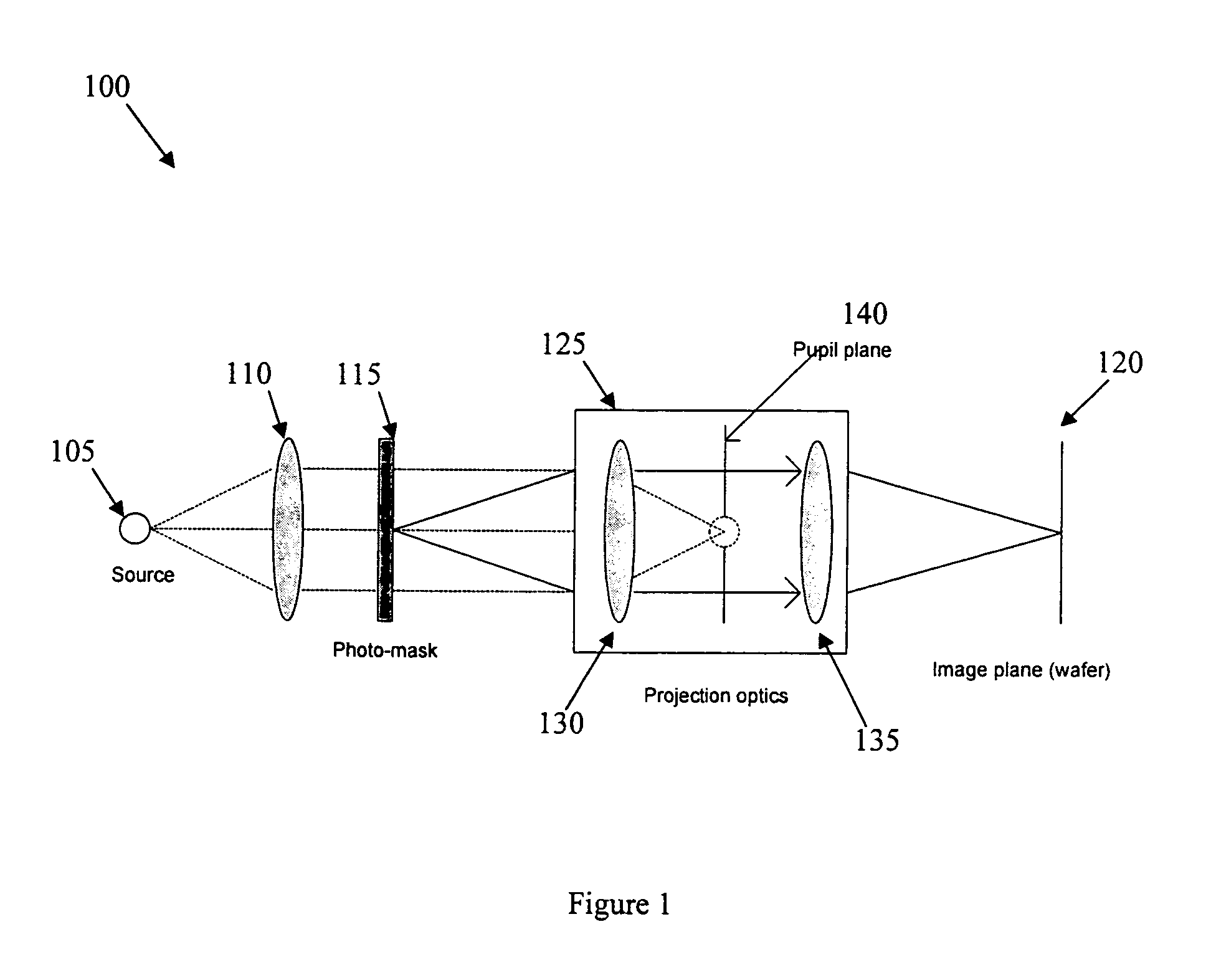
[0045]Referring now to FIG. 1, the optical stepper 100 being used in photolithography is a reduction optical imaging system combined with a partially coherent illuminating source 105. The condenser unit 110 provides collimated exposure light to the photo-mask 115, which is in the object plane of stepper 100. The exposing light is diffracted by the mask 115 and imaged through the stepper 100 onto the image plane on the wafer 120. The reduction ratio of this imaging is often 5×, which means that features on the wafer are five times smaller than the corresponding objects on mask. The imaging part 125 of the stepper 1...


PUM


Abstract

Methods and systems of creating a photo-mask to form continuous relief micro-structures in photo-active material. This technology uses a basic amplitude mask or electron-beam to create a binary phase grating with pi-phase depth on a transparent reticle coated with photo-active material. The reticle is then used as a phase mask for the fabrication of analog micro-elements. The mask is used in an image reduction machine such as an optical stepper. The period and duty cycle of the phase gratings can be varied to create the proper analog intensity for the desired micro-profile on the photo-active material. The design, analysis, and fabrication procedure of this invention for prisms and positive micro-lenses has been demonstrated.

Description


Claims


Application Information

Patent Timeline
Owner JOHNSON ERIC G
Why Eureka
Try Eureka