Apparatus for milling material

a technology of apparatus and material, which is applied in the field of apparatus for milling material, can solve the problems of inability to reproduce bone powder, damage to bone particles, and general suffering of bone mills, and achieve the effect of facilitating material milling

Active Publication Date: 2009-09-15
RASEKHI HOUSHANG
View PDF30 Cites 15 Cited by
  • Summary
  • Abstract
  • Description
  • Claims
  • Application Information

AI Technical Summary

Benefits of technology

[0007]An apparatus for milling material to a predetermined particle size distribution profile is disclosed. The apparatus includes a base surface. The base surface includes a first cutting tooth for milling the material. The base surface also includes a first aperture of a predetermined diameter disposed adjacent the first cutting tooth so that material of less than the predetermined diameter may pass through the first aperture. The apparatus also includes a trimming member. The trimming member includes a first rib for interfacing with the first cutting tooth to facilitate the milling of the material. The base surface and the trimming member move relative to each other and interface to mill material placed on the base surface.
[0013]Another embodiment of an apparatus for milling material to within a predetermined particle size distribution profile is described. The apparatus includes a base surface. The base surface includes a first cutting tooth for milling the material. The base surface also includes a first aperture of a predetermined diameter disposed adjacent the first cutting tooth so that material of less than the predetermined diameter may pass through the first aperture. The apparatus includes a trimming member. The trimming member includes a first rib for interfacing with the first cutting tooth to facilitate the milling of the material. The base surface and the trimming member move longitudinally relative to each other and interface to mill material placed on the base surface.
[0017]A further embodiment of an apparatus for milling material to within a predetermined particle size distribution profile is described. The apparatus includes a base surface. The base surface includes a first cutting tooth for milling the material. The base surface also includes a first aperture of a predetermined diameter disposed adjacent the first cutting tooth so that material of less than the predetermined diameter may pass through the first aperture. The apparatus includes a trimming member. The trimming member includes a first rib for interfacing with the first cutting tooth to facilitate the milling of the material. The base surface and the trimming member move radially relative to each other and interface to mill material placed on the base surface.

Problems solved by technology

The available bone mills generally suffer from either inability to reproduce bone powder with predictable bone particle size distribution or damage the bone particles by transferring degrading heat to the bone particles.
These problems may also arise in other milling contexts.

Method used


Image

  • Apparatus for milling material
  • Apparatus for milling material
  • Apparatus for milling material

Examples


Embodiment Construction

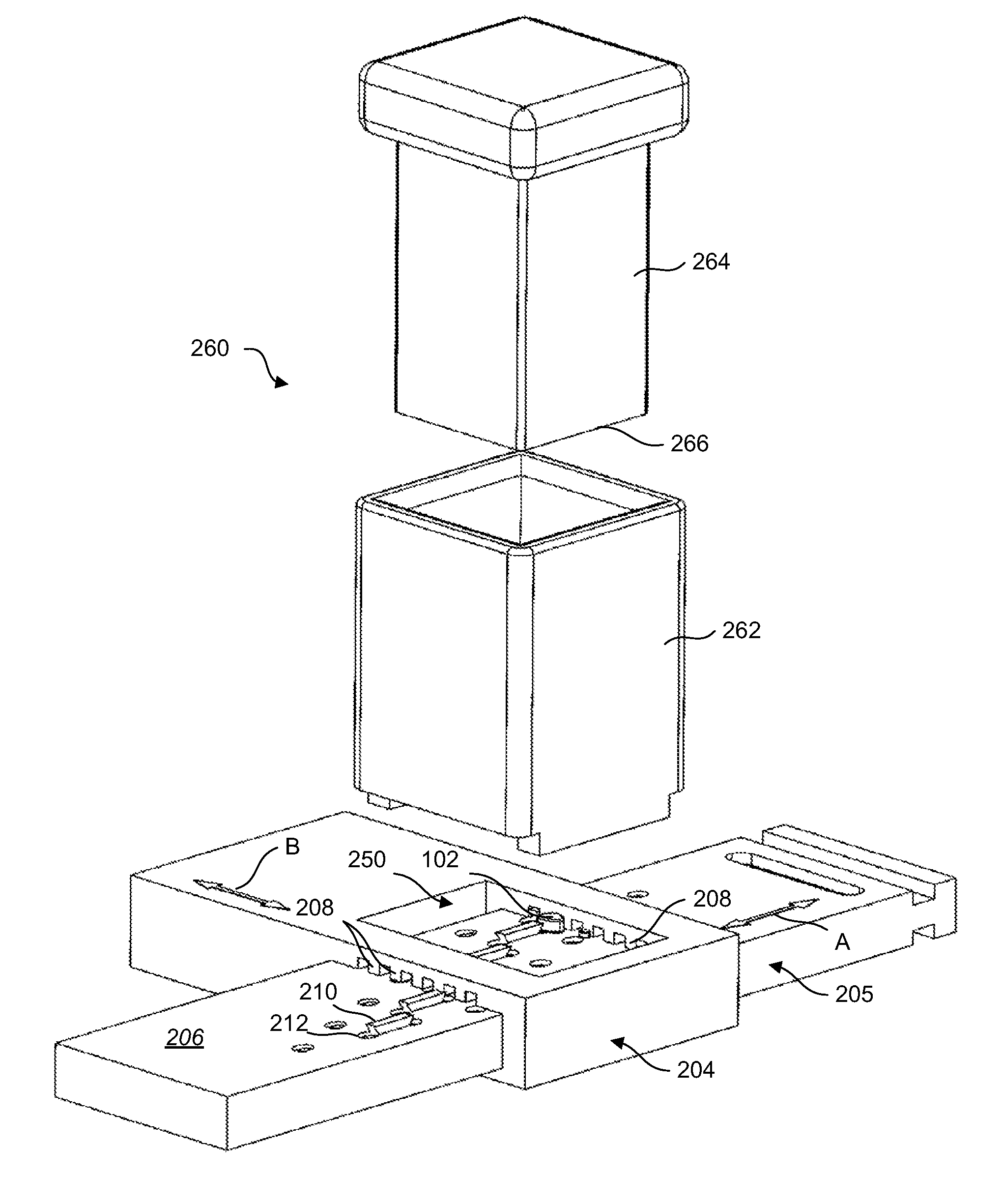
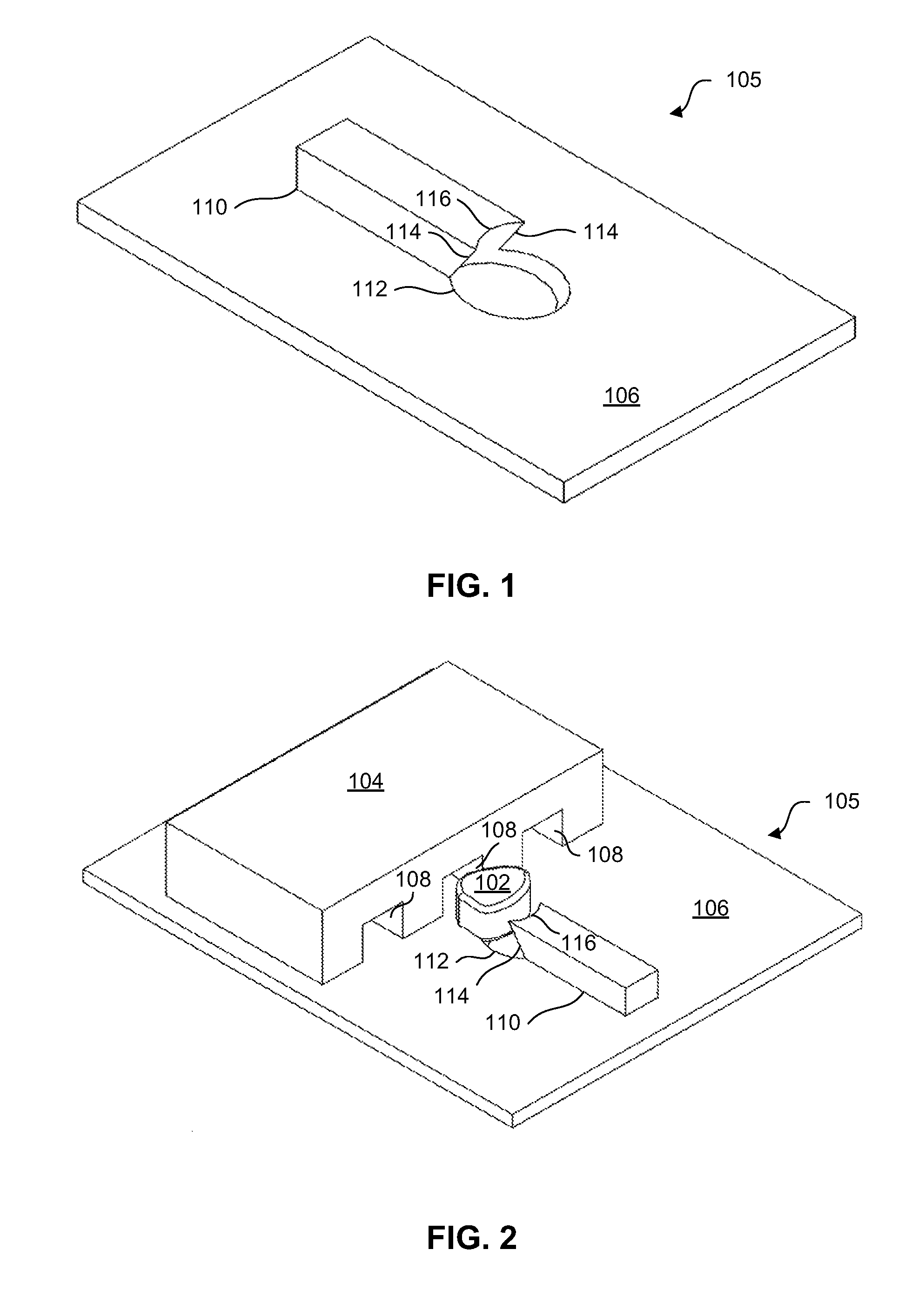
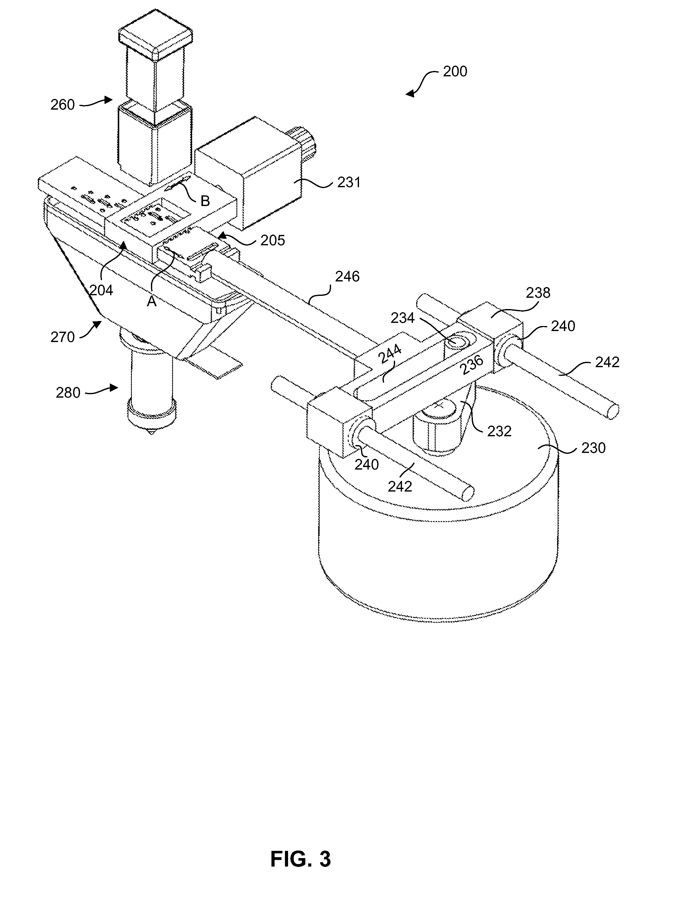
[0035]Various embodiments of the invention are now described with reference to the Figures, where like reference numbers indicate identical or functionally similar elements. The embodiments of the present invention, as generally described and illustrated in the Figures herein, could be arranged and designed in a wide variety of different configurations. Thus, the following more detailed description of several exemplary embodiments of the present invention, as represented in the Figures, is not intended to limit the scope of the invention, as claimed, but is merely representative of the embodiments of the invention.

[0036]The word “exemplary” is used exclusively herein to mean “serving as an example, instance, or illustration.” Any embodiment described herein as “exemplary” is not necessarily to be construed as preferred or advantageous over other embodiments.

[0037]As used herein, the terms “an embodiment,”“embodiment,”“embodiments,”“the embodiment,”“the embodiments,”“one or more embo...


PUM


Abstract

An apparatus for milling material is disclosed. The apparatus may include a base surface. The base surface may include a first cutting tooth for milling the material. The base surface may include a first aperture of a predetermined diameter. The first aperture may be disposed adjacent the first cutting tooth so that material of less than the predetermined diameter may pass through the first aperture. The apparatus may include a trimming member. The trimming member may include a first rib for interfacing with the first cutting tooth to facilitate the milling of the material. The base surface and the trimming member may move relative to each other. The base surface and the trimming member may interface to mill material placed on the base surface.

Description

RELATED APPLICATIONS[0001]This application is related to and claims priority from Provisional U.S. Patent Application Ser. No. 60 / 759,475 filed Jan. 17, 2006, for a New and Improved Bone Mill with Vacuum Mixing System, with inventor Houshang Rasekhi and Provisional U.S. Patent Application Ser. No. 60 / 812,867 filed Jun. 12, 2006, for a New and Improved Bone Mill with Reciprocating Self-Clearing Rasp and Vacuum Mixing System, with inventor Houshang Rasekhi which are both incorporated herein by reference. The present specification focuses on general elements of the present invention. By doing so, Applicant does not intend to limit the scope of the present invention.TECHNICAL FIELD[0002]The present invention relates generally to milling devices. More specifically, the present invention relates to an apparatus for milling material, particularly bone material.BACKGROUND[0003]Bone grafting is often used in orthopedic procedures to either stimulate bone to heal or provide support to the ske...

Claims


Application Information

Patent Timeline
Patent Type & Authority Patents(United States)
IPC IPC(8): B02C18/16
CPCA61F2/4644B02C19/20B02C19/0056A61F2002/4645Y10S241/606
Inventor RASEKHI, HOUSHANG
Owner RASEKHI HOUSHANG
Why Eureka
Try Eureka