Method and apparatus for noise abatement and ice protection of an aircraft engine nacelle inlet lip

a technology of ice protection and aircraft engine, which is applied in the direction of de-icing equipment, fuselage insulation, aircraft power plants, etc., can solve the problems of engine malfunction, loss of performance, and varying amounts of objectionable audible noise of aircraft airframe and engine during departure and approach conditions, so as to avoid temperature concerns, weight and cost penalties, the effect of improving ice protection and acoustic performance characteristics

Inactive Publication Date: 2009-09-15
ROHR INC
View PDF22 Cites 71 Cited by
  • Summary
  • Abstract
  • Description
  • Claims
  • Application Information

AI Technical Summary

Benefits of technology

[0013]This invention advantageously increases the amount of acoustic treatment that may be applied to the nacelle inlet area, for maximizing noise reduction. Use of the invention also permits the power plant designer to reduce the inlet structure weight, by shortening the inlet structure. This may be done because use of the invention allows more sound suppression panels to be incorporated into the nacelle, per unit length of the nacelle, than do prior art ice protection systems. Accordingly, if the power plant designer wishes to build a nacelle with the same amount of sound suppression panel as a prior art nacelle, by using the present invention the length of the nacelle may be reduced, which in turn reduces the weight of the nacelle. Additionally, a reduced length nacelle allows the fan case to be smaller, and lighter.
[0014]A further advantage of this invention results from the increasing desire in the industry to make nacelle de-icing and anti-icing systems completely electrically powered. Although current nacelle systems often employ engine bleed air for de-icing, hydraulics for thrust reverser actuation, and multiple electronic sub-systems, future designs will benefit by replacing hot air systems with electrical ice protection systems to improve engine power efficiency, and replace hydraulic actuators with electric actuators to reduce weight. The method and apparatus of this invention provide an electric de-icing and anti-icing solution to accomplish at least a portion of this goal, and also provide the acoustic and weight savings benefits discussed above, as well as additional positive features and advantages as discussed below.
[0016]It is another object of this invention to provide an aircraft gas turbine engine nacelle with improved ice protection and acoustic performance characteristics. The nacelle has an inlet lip comprising an acoustic panel structure including a solid back skin, an acoustically permeable front skin, and a honeycomb cell structure therebetween, and the inlet lip further comprises an ice protection system on the front skin of the panel. The ice protection system includes an acoustically permeable and electrically and thermally conductive structure in connection with an electric power source, and thermally insulated from the permeable front skin.
[0017]By employing a low power electrically powered ice protection system, the area available for application of the noise abatement structure (e.g. honeycomb panel) may be increased while avoiding the temperature concerns typically associated with combining such a noise abatement structure in proximity to a conventional hot air de-icing and anti-icing system. Moreover, there is advantageously no required increase to the inlet length to accommodate placement of the noise abatement structure to achieve noise suppression; thus the associated weight and cost penalties associated with such an inlet length increase are advantageously avoided.
[0018]Alternatively, if the external nacelle surfaces are initially sized assuming the use of no noise abatement structure in the inlet lip area, using the present invention it is possible to actually reduce the length of the inlet, because application of this invention permits the use of a noise abatement structure within the nacelle inlet lip, thus reducing the barrel length required for application of the noise abatement structure to achieve noise reduction, thereby permitting reduction of the barrel length via subsequent modification. This optimization or reduction in length is desirable for the following reasons: first, shortening the inlet provides a decrease in weight; second, a shorter inlet will reduce external drag and improve fuel consumption; and third, less material costs are incurred.
[0019]Furthermore, the use of an electrically powered ice protection system, rather than a hot air system, eliminates the need for pressure relief doors in both the fan and inlet cowls (depending on engine configuration), thereby providing additional weight and cost benefits. Moreover, hot air de-icing systems typically employ pneumatic valves to deliver the hot air to the appropriate location. Eliminating the use of such pneumatic valves eliminates the need for devices that are frequently removed for service or replacement. Pneumatic valves remain the primary field problem causing system failure for hot air de-icing systems, resulting in high warranty returns and customer frustration due to the lack of valve reliability. In addition, the weight and cost associated with the use of such valves is advantageously eliminated.

Problems solved by technology

As discussed, for example, in U.S. Pat. No. 5,749,546, both the airplane's airframe and engine produce varying amounts of objectionable audible noise during departure and approach conditions.
With respect to the engines, ice breaking away from the engine inlet can damage various components if ingested into the engine.
The formation of ice in this region also constricts the flow of air into the engine, causing losses of performance and potential engine malfunction.
This is an expensive procedure, which may require repeated application of the glycol solution.
This option is not available for aircraft that do not have jet engines, or aircraft limited in the amount of hot air that can be bled off the engine.
However, the use of engine bleed air for ice protection can negatively impact engine performance, and dictates that additional engine nacelle design requirements and conditions be considered.
Utilizing compressed air for ice protection is an energy loss and results in propulsion system inefficiency.
The resulting requirement of hot air ice protection systems is a significant performance penalty incurred by the engine on take-off.
However, the portion of the engine nacelle inlet lip available for acoustic treatment is currently limited to the inner barrel structure aft of the inlet lip, due mainly to the incompatibility of the prior art hot air de-icing systems with the relatively low temperature capability of existing, adhesively bonded honeycomb noise abatement structures.
There is a lack of current technology that provides a satisfactory method for extending such engine noise reduction structures into the nacelle lip while concurrently satisfying the temperature constraints of the noise abatement treatment.

Method used


Image

  • Method and apparatus for noise abatement and ice protection of an aircraft engine nacelle inlet lip
  • Method and apparatus for noise abatement and ice protection of an aircraft engine nacelle inlet lip
  • Method and apparatus for noise abatement and ice protection of an aircraft engine nacelle inlet lip

Examples


Embodiment Construction

[0026]This invention will be further understood in view of the following detailed description.

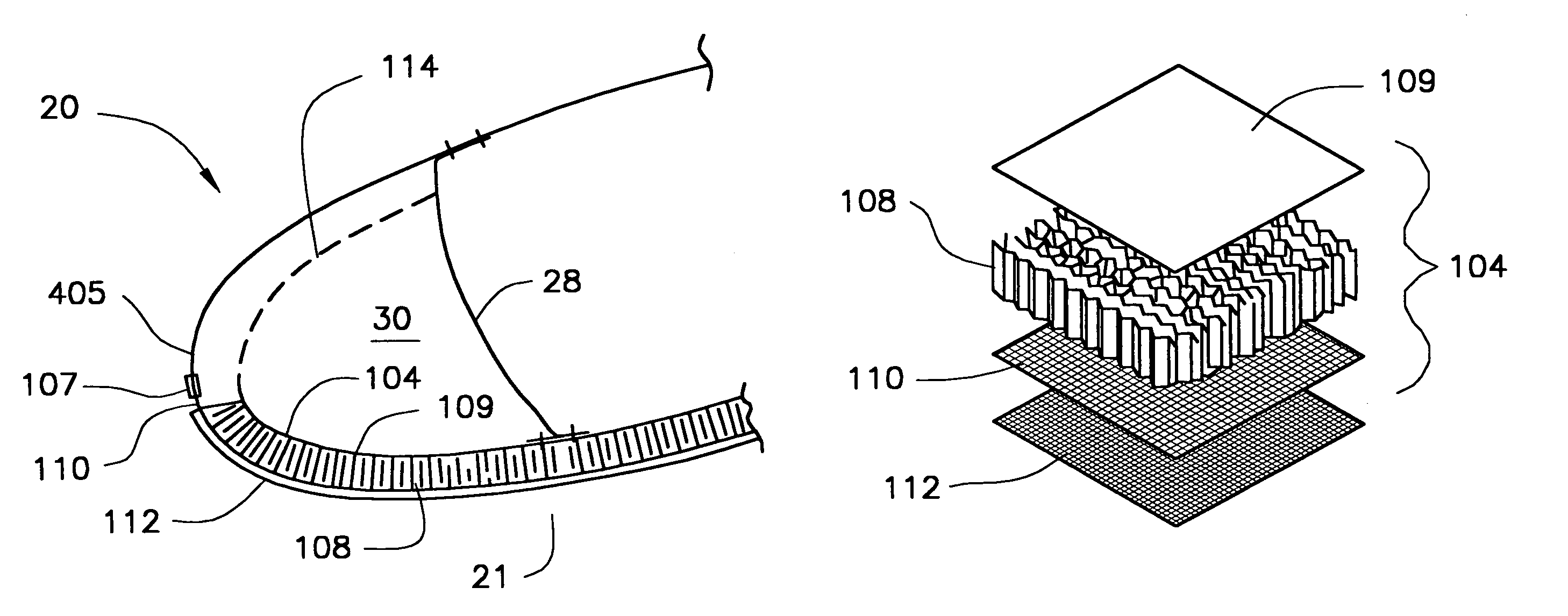
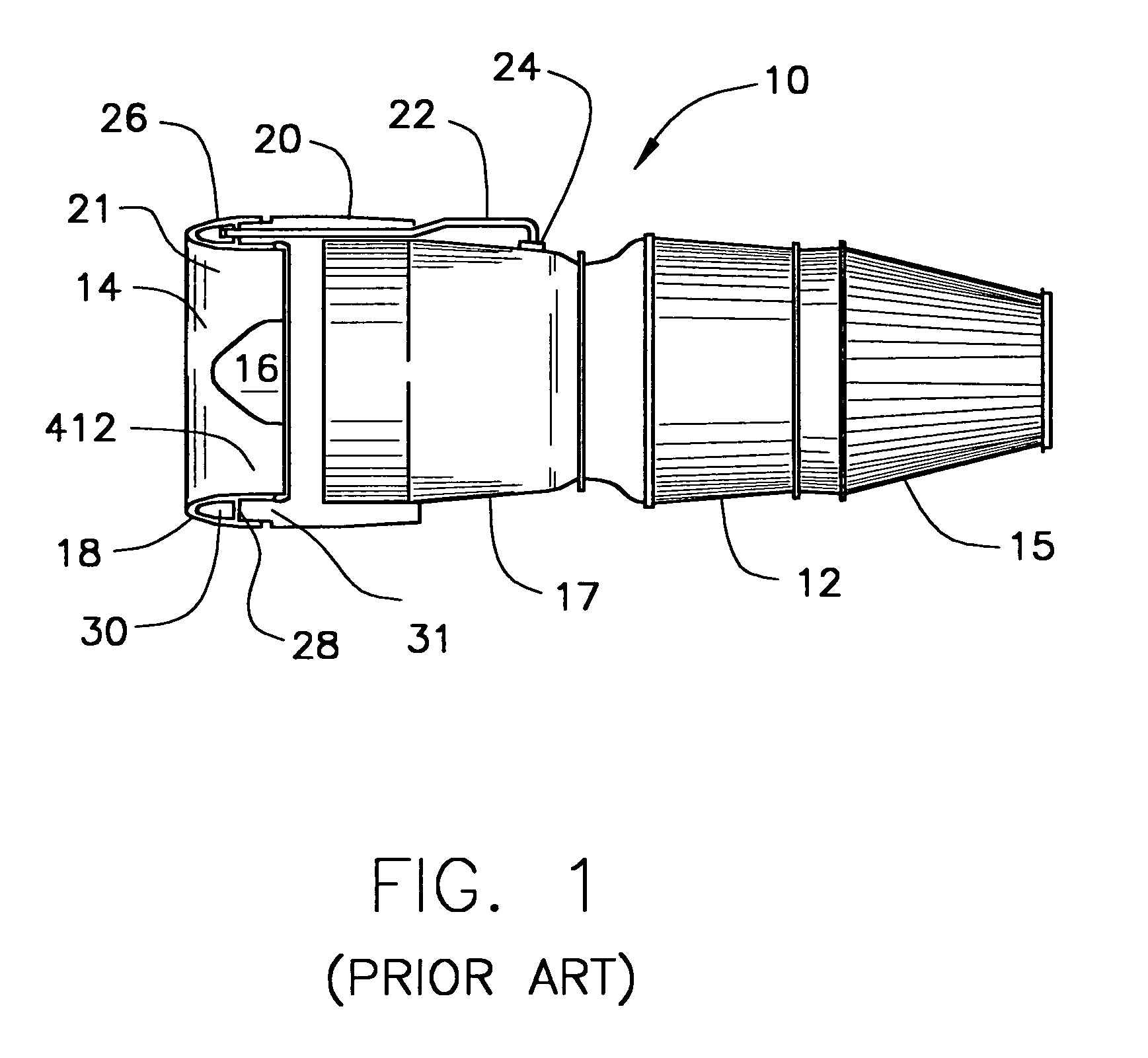
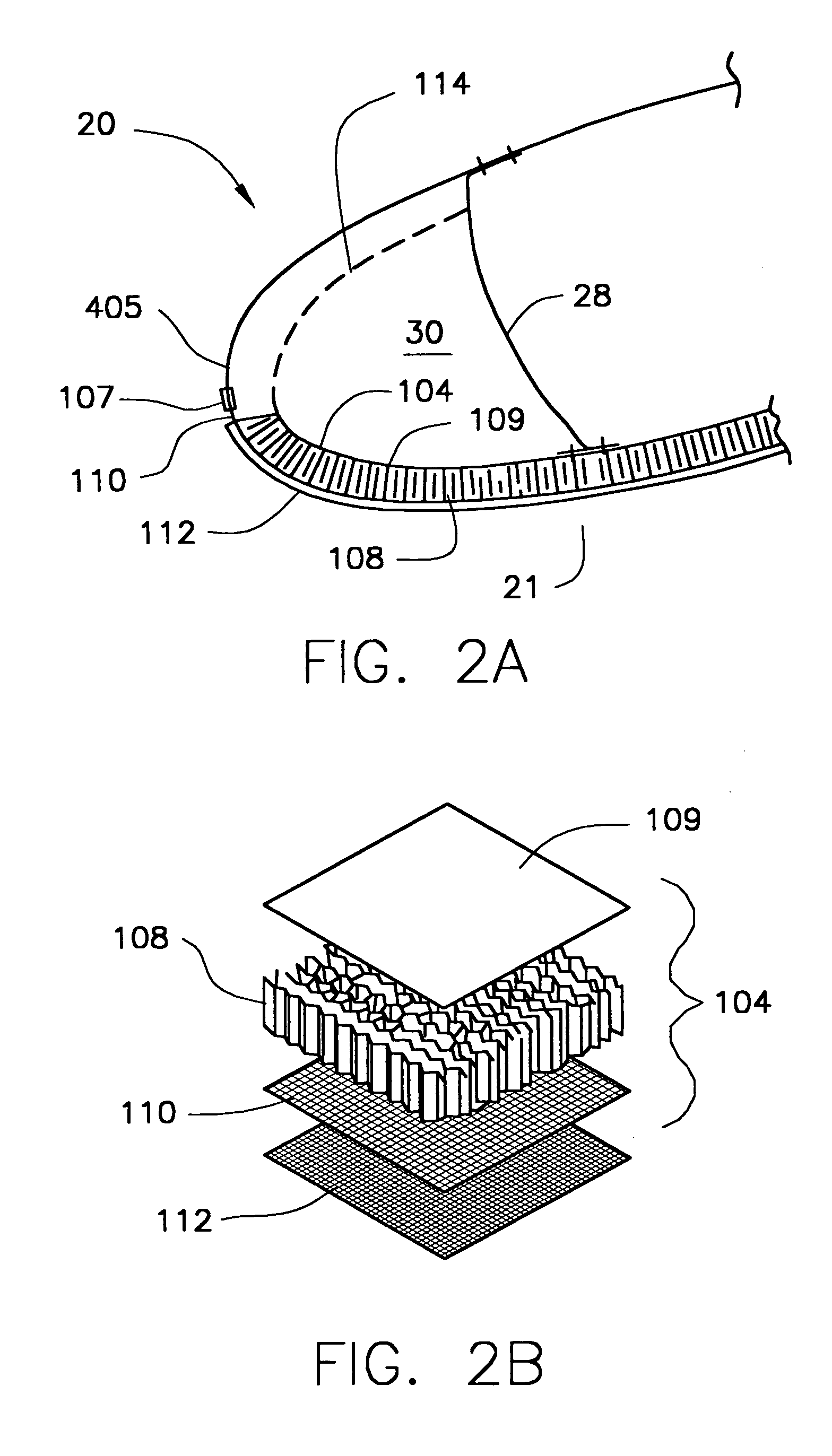
[0027]Referring now to FIG. 1, which is also set forth in U.S. Pat. No. RE 36,215, there is seen a schematic representation of a high-speed jet engine 10 of the sort suitable for aircraft propulsion. Air enters through inlet section 14, between nose cap 16 and the annular housing 18, which constitutes the forwardmost section of the engine nacelle 20, which includes nacelle inlet lip 21. Hot, high-pressure propulsion gases pass through exhaust assembly 15 and out the rear of the engine.

[0028]In flight, under certain temperature and humidity conditions, ice may form on the nacelle inlet lip 21, which is the leading edge of annular housing 18, and on the nose cap 16. The ice changes the geometry of the inlet area between annular housing 18 and nose cap 16, adversely affecting the quantity and flow path of incoming air. Also, pieces of ice may periodically break free from these components and e...


PUM


Abstract

An aircraft engine nacelle comprises: (a) an inlet lip and a skin having internal and external surfaces; (b) a noise abatement structure such as an acoustic panel located on the internal surface of the nacelle skin; and (c) an electrically powered de-icing system located on the external surface of the nacelle skin and in electrical connection to a power source. A method for de-icing and abating noise from an aircraft nacelle comprises: (a) providing a noise abatement structure such as an acoustic panel located on the internal surface of the nacelle skin; (b) providing an electrically powered de-icing system on the external surface of the nacelle skin; and (c) applying an electric current to the electrically powered de-icing system. The nacelle skin may be a perforated skin, and the de-icing system comprises a wire mesh bonded to the external surface of the perforated skin. The method and nacelle permit the use of noise abatement structures such as acoustic panels for noise reduction while advantageously avoiding detrimental high temperatures associated with conventional de-icing systems.

Description

BACKGROUND OF THE INVENTION[0001]1. Field of the Invention[0002]This invention relates to an apparatus and method for reducing the noise of an aircraft gas turbine engine, while at the same time improving de-icing and anti-icing performance in the area of the aircraft engine's nacelle. More particularly, this invention relates to a method and apparatus for reducing noise generated by the fan section of the aircraft engine and concurrently employing a low power electrical ice protection system to minimize ice formation on the nacelle inlet and remove any ice formed on the nacelle inlet. One or more sound-absorbing or noise abatement structures are employed at the inner surface of the nacelle inlet lip to reduce noise. The use of the low power electrical ice protection system enables the use of such structures for noise abatement in the inlet lip area while simultaneously permitting the installation and use of necessary ice protection equipment on the nacelle inlet.[0003]2. Background...

Claims


Application Information

Patent Timeline
Patent Type & Authority Patents(United States)
IPC IPC(8): B64D15/12B64C1/40B64D33/02
CPCB64D15/12B64D33/02B64D2033/0233B64D2033/0206
Inventor MOE, JEFFREY W.WUNSCH, JOHN J.SPERLING, MICHAEL S.
Owner ROHR INC
Why Eureka
Try Eureka