Exhaust temperature based control strategy for balancing cylinder-to-cylinder fueling variation in a combustion engine

a technology of exhaust temperature and control strategy, which is applied in the direction of liquid fuel feeders low-pressure fuel injection, etc., can solve the problem of limited change to the actuation waveform of respective injectors

Inactive Publication Date: 2009-09-22
CATERPILLAR MOTOREN
View PDF14 Cites 6 Cited by
  • Summary
  • Abstract
  • Description
  • Claims
  • Application Information

AI Technical Summary

Benefits of technology

[0008]In order to prevent major malfunctions or damage to the combustion engine from going undetected, the number of changes for each injector is preferably limited to a certain number. In this way, changes to the exhaust gas temperature which are not due to tolerance differences of the injectors or which are not based upon the amount of fuel injected, can be prevented from going unnoticed. Furthermore, the amount of each incremental change to the injector actuation waveform may correspond to a predetermined value in order to achieve uniform equalization of the exhaust gas temperatures. In addition, the total amount of the change to the actuation waveform of a respective injector may be limited. This may be useful to prevent changes to an injector waveform when the exhaust gas temperature deviation of a combustion chamber is either not due to tolerance differences of the injectors, or not based upon the amount of fuel injected. In these cases, adjusting the injector actuation waveform could prevent major malfunctions from being detected. The amount of any change or the total amount of the change(s) to the actuation of a respective injector may be determined as a percentage of the unchanged actuation according to the original fuel request map. Normal actuation of the injector according to the original fuel request map is therefore used as the basis for limiting the extent of each individual change or the total extent of the change(s). A larger or smaller change is therefore possible depending on the fuel request map. For example, when operating the combustion engine under normal load conditions, smaller changes to the actuation are possible than when operating in full or overload conditions of the engine. The maximum overall extent of the change(s) comes within a range of between 1 and 10%, and may be 4%, as flow rate tolerances for the injectors come within this range.
[0009]The above procedure may be repeated cyclically in order to provide a corresponding optimization during the engine operation. After a change to the actuation waveform of an injector, a predetermined period of time may elapse before the repetition of the steps. This period of time should be long enough so the system may be given the possibility of stabilizing a change to the exhaust gas temperature brought about by the change to the actuation waveform of an injector. In some variants, the change settings and change history are recorded. This type of recording makes it possible to determine irregularities when checking the engine. Furthermore, recording the change settings makes it possible for the settings to be maintained when the combustion engine is restarted. If the changes are due to production tolerances of the fuel supply system, when the engine is restarted it can be operated directly with the previously optimized settings. In an alternative variant of the disclosure, the change values may be reset when the combustion engine is restarted.

Problems solved by technology

In addition, the total amount of the change to the actuation waveform of a respective injector may be limited.

Method used


Image

  • Exhaust temperature based control strategy for balancing cylinder-to-cylinder fueling variation in a combustion engine
  • Exhaust temperature based control strategy for balancing cylinder-to-cylinder fueling variation in a combustion engine
  • Exhaust temperature based control strategy for balancing cylinder-to-cylinder fueling variation in a combustion engine

Examples


Embodiment Construction

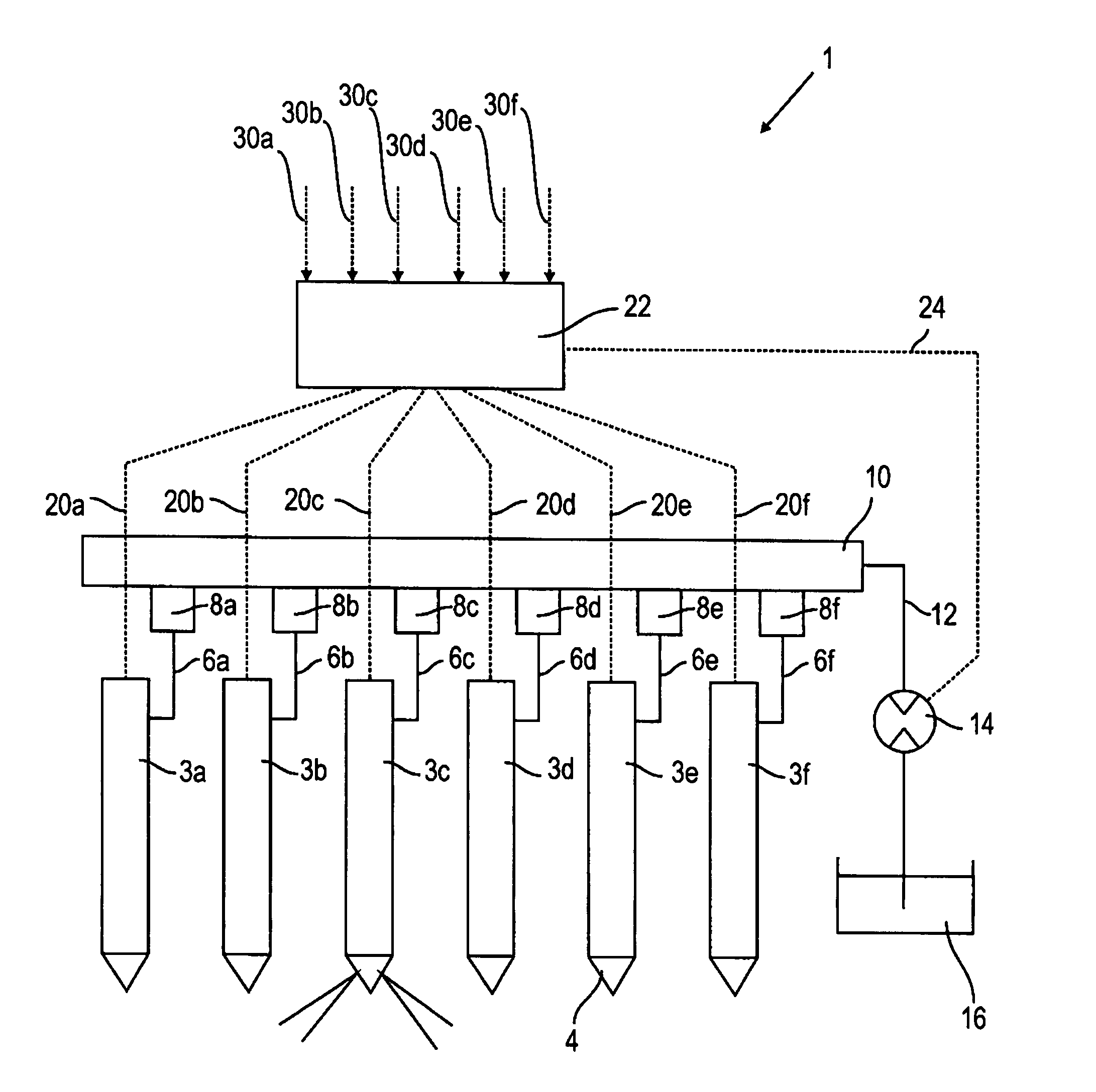
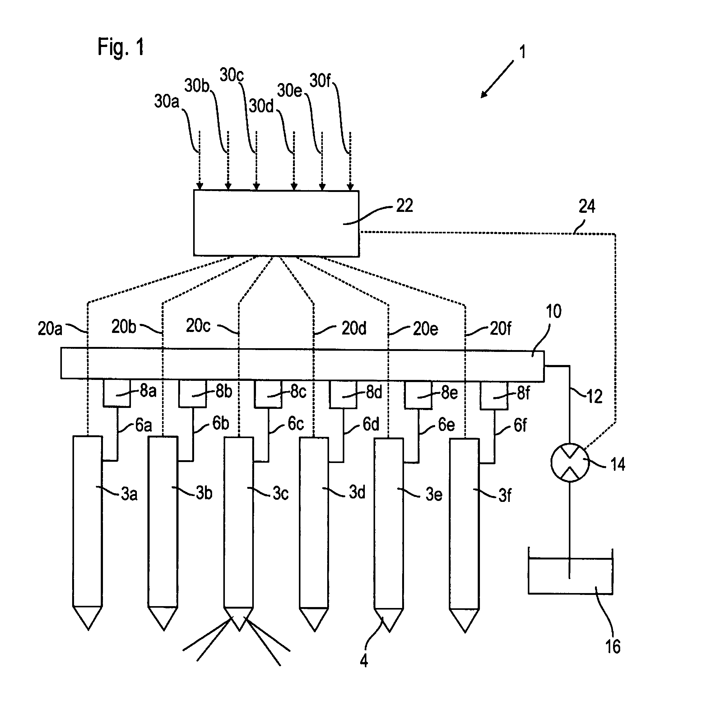
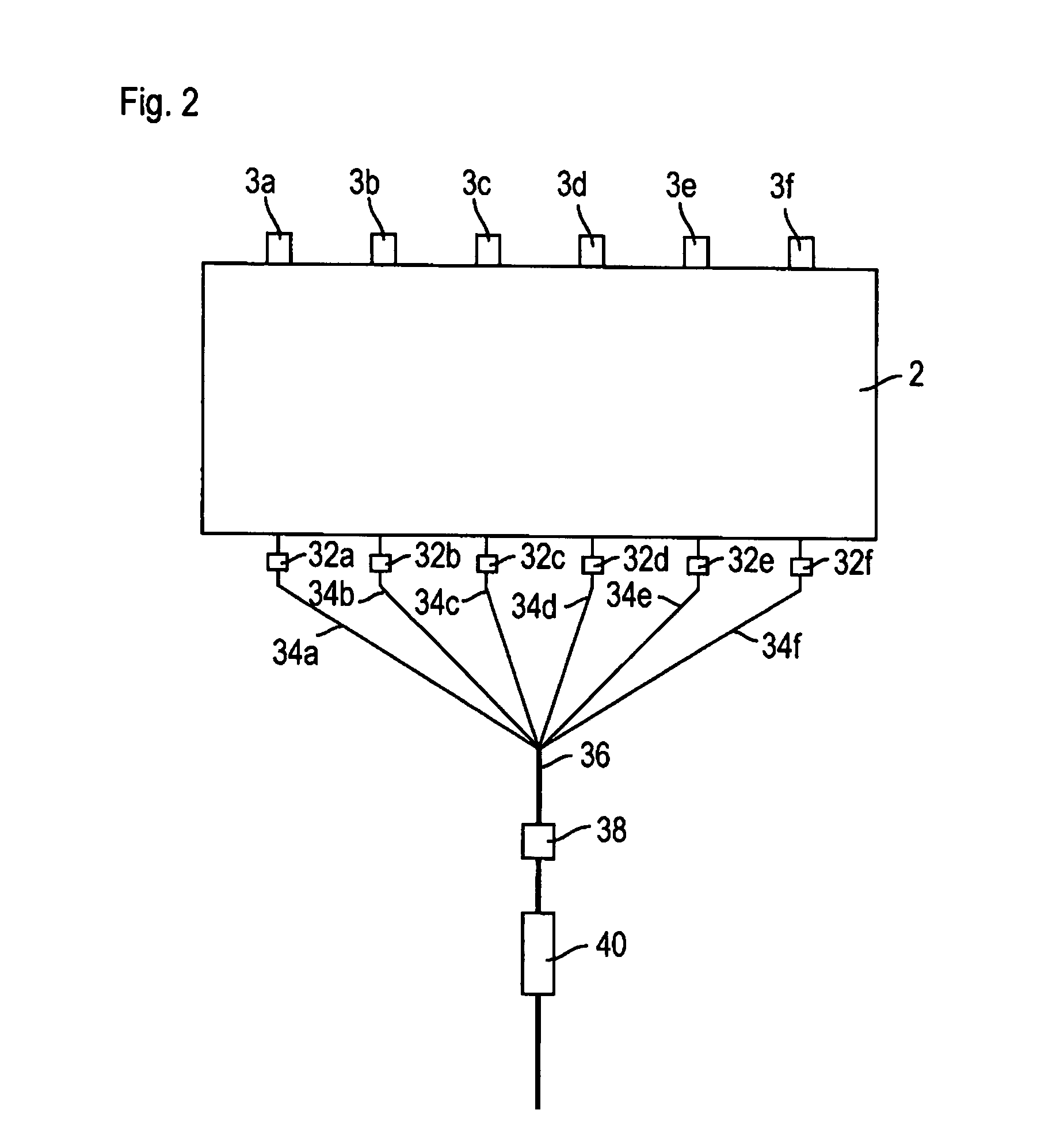
[0016]FIGS. 1 and 2 schematically show the structure of a control system (1) for a combustion engine (2) having multiple combustion chambers (and cylinders) (not shown). For simplification of the illustration, the combustion engine (2) is only shown schematically in FIG. 2. However, FIG. 1 shows multiple injectors (3a to 3f), an injector being assigned to each combustion chamber of the combustion engine (2). The injectors (3a to 3f each have a nozzle tip (4) pointing into the corresponding combustion chamber for injecting fuel into the combustion chamber. Although six injectors are shown in the figures, a different number of injectors (and combustion chambers) may be provided.

[0017]The injectors (3a to 3f) are respectively connected by a fuel line (6a to 6f) and a flow limiting valve (8a to 8f) to a common high pressure rail (10), generally called a common rail. The flow limiting valves have a flow rate limited quantity which is chosen for the whole performance range of the engine f...


PUM


Abstract

The present disclosure provides a control strategy for balancing injector-to-injector fueling variations for a combustion engine having multiple combustion chambers (and cylinders), with multiple individually actuated injectors for injecting fuel into the combustion chambers, wherein at least one injector is assigned to each combustion chamber and a common rail supplies fuel to the multiple injectors. The method includes changing the actuation waveform of an injector assigned to a combustion chamber having an exhaust gas temperature deviating by more than the predetermined value from the average exhaust gas temperature, in order to change the amount of fuel injected.

Description

TECHNICAL FIELD[0001]The present disclosure relates to an exhaust temperature based control strategy for balancing cylinder-to-cylinder fueling variation in a combustion engine and, more particularly, to a combustion engine having a common rail injection system.BACKGROUND[0002]Combustion engines with a common rail injection system are generally known. In this type of combustion engine multiple combustion chambers (and cylinders) are provided. An injector is allocated to each combustion chamber, with each injector connected to a common high pressure rail, (generally called a common rail) for supplying fuel. In common rail systems, due to production tolerances of the injectors (along with other contributing factors), variations with regard to the quantity of fuel injected by individual injectors occur. These differences in the quantity of fuel injected lead to variations in the respective exhaust gas temperatures of the combustion chambers.[0003]One known method to account for this va...

Claims


Application Information

Patent Timeline
Patent Type & Authority Patents(United States)
IPC IPC(8): F02D41/00F02M69/46
CPCF02D41/008F02D41/1446F02D41/0235F02D41/3809F02D41/22
Inventor NAGEL, JUERGENRITSCHER, BERTSCHROEDER, ALAN R.
Owner CATERPILLAR MOTOREN
Why Eureka
Try Eureka