Cutting insert with serrations

a cutting insert and serration technology, applied in the field of milling cutters, can solve the problems of many insert styles, cumbersome and inflexible, and high cost of rough surface finish

Inactive Publication Date: 2009-09-22
KENNAMETAL INC
View PDF11 Cites 32 Cited by
  • Summary
  • Abstract
  • Description
  • Claims
  • Application Information

AI Technical Summary

Problems solved by technology

However, this is achieved at the expense of rougher surface finish.
This is cumbersome and inflexible, and requires many insert styles in some cases.
In addition, possible body damage may occur if improper inserts are not in the appropriate pockets.

Method used


Image

  • Cutting insert with serrations
  • Cutting insert with serrations
  • Cutting insert with serrations

Examples


Embodiment Construction

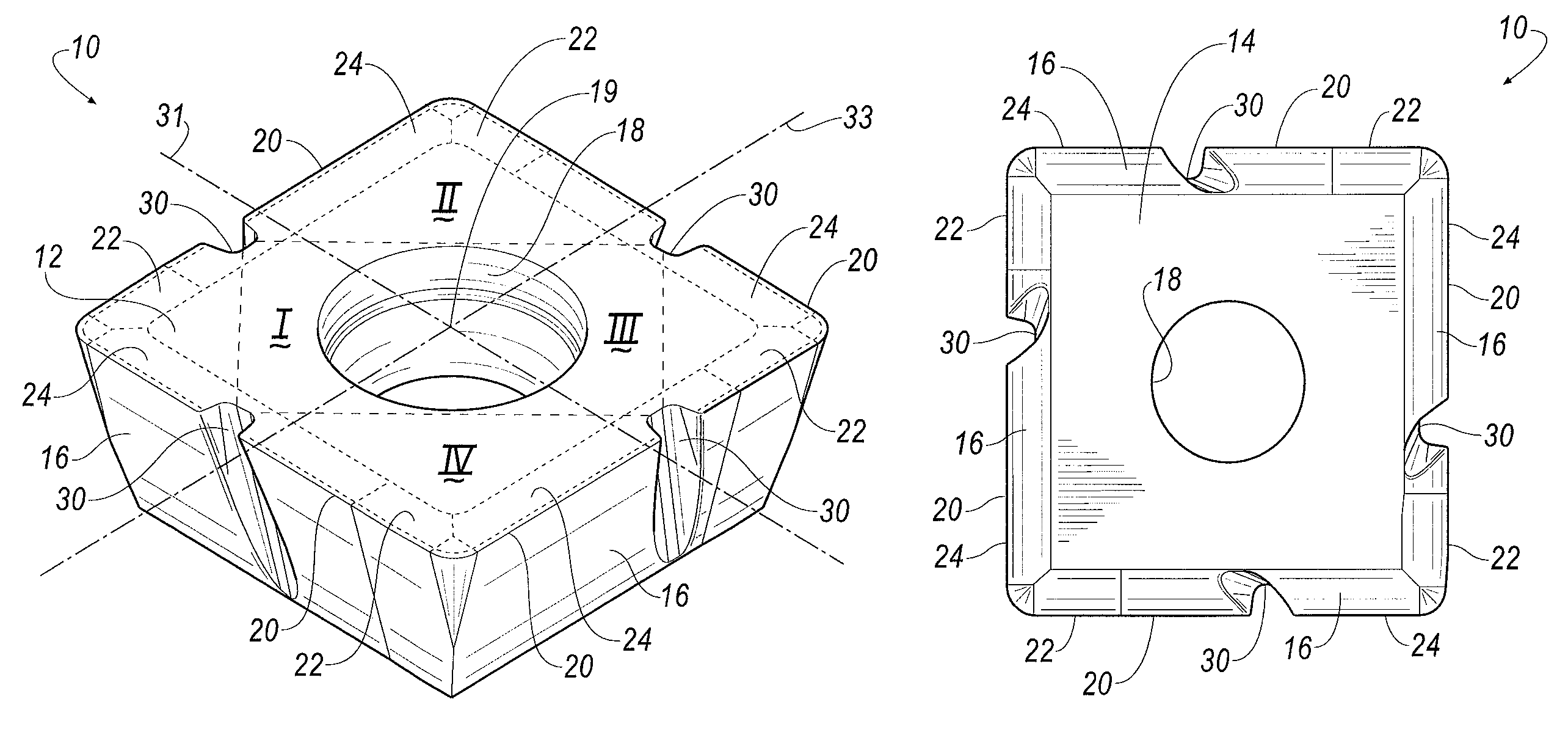
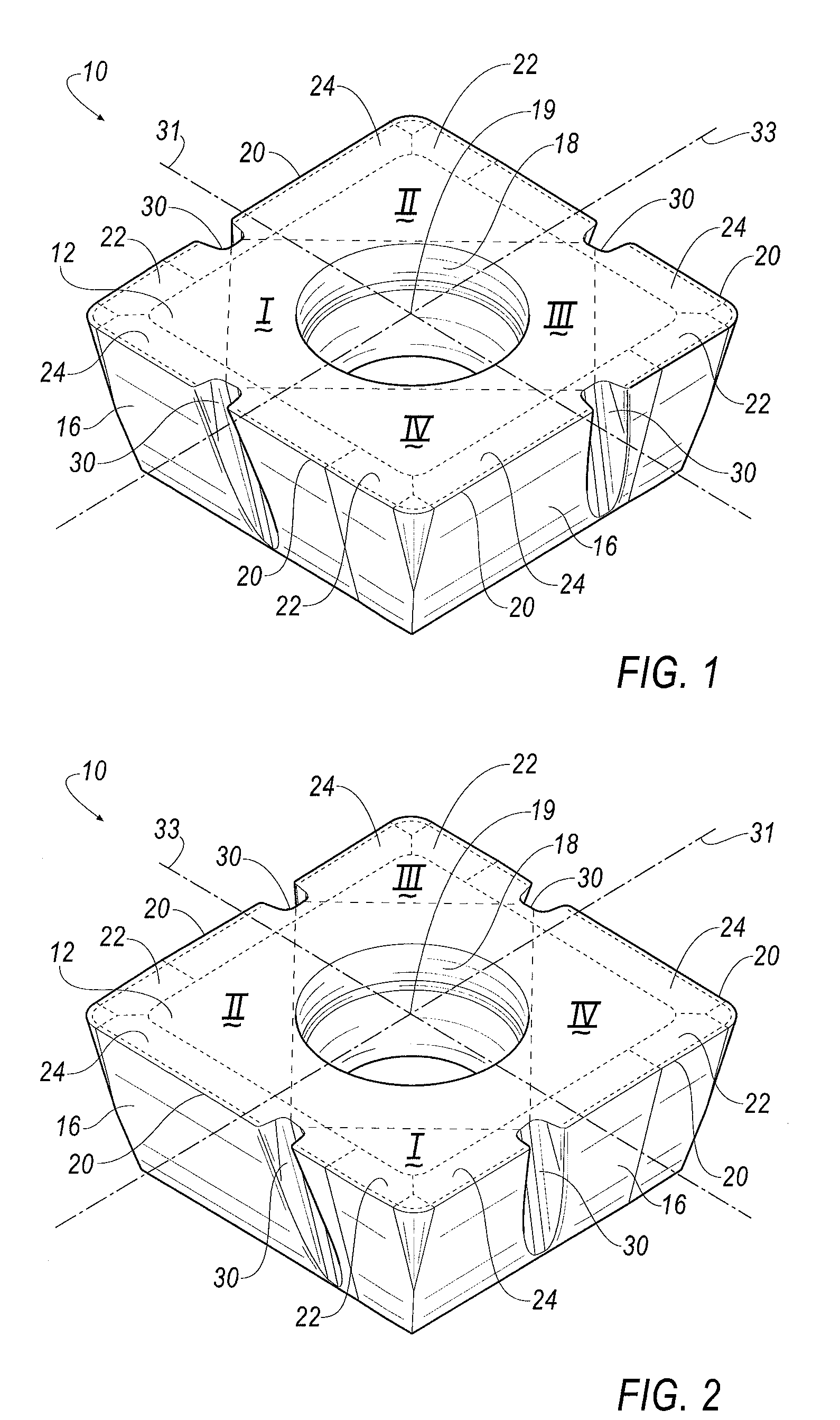
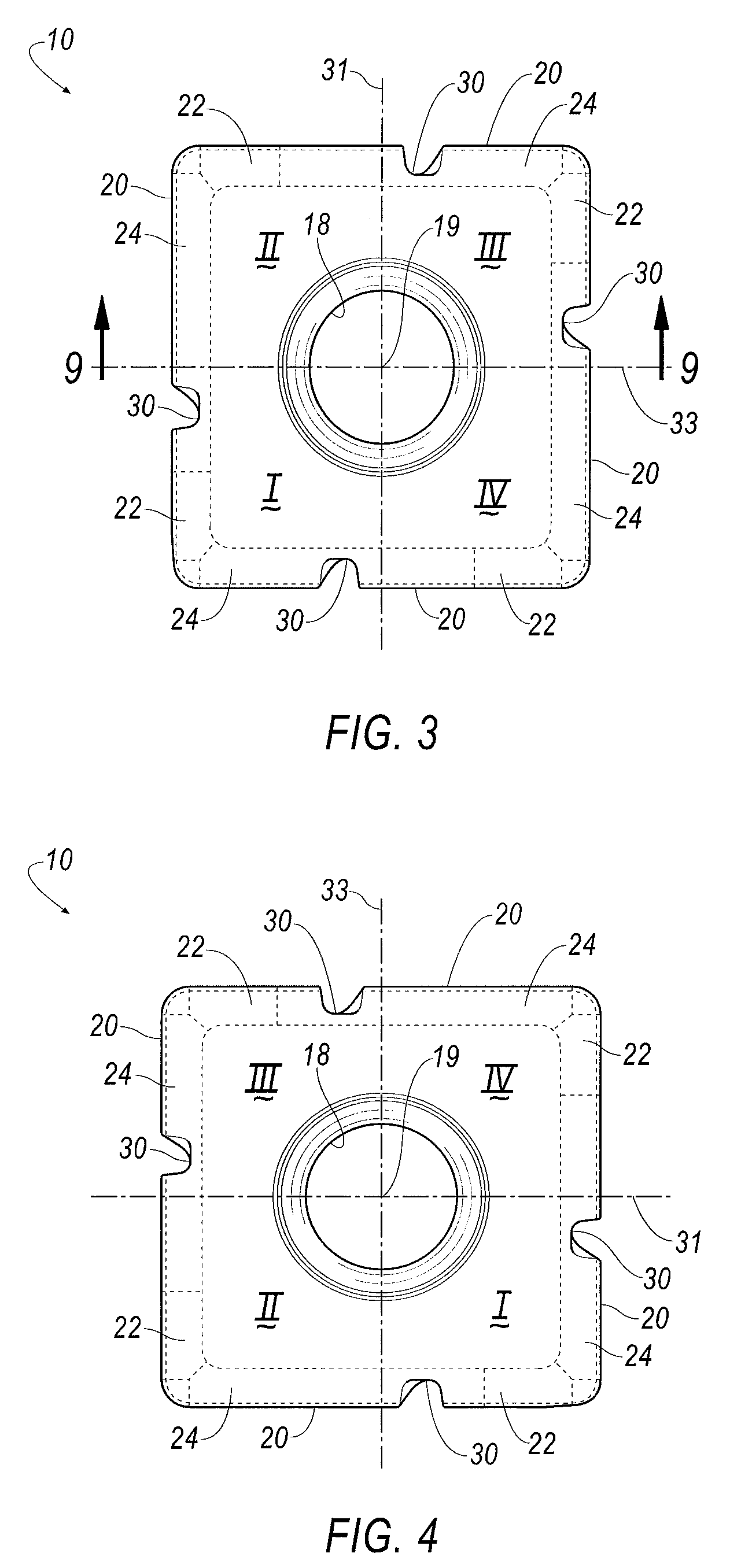
[0023]Referring now to FIGS. 1-10, a replaceable and indexable cutting insert according to an embodiment of the invention is shown generally at 10. The cutting insert 10 includes a top surface 12, a bottom surface 14 and a plurality of clearance side surfaces 16. A countersunk bore 18 extends from the top surface 12 to the bottom surface 14. The bore 18 is capable of accommodating a fastener, for example, a screw (not shown), for securing the cutting insert 10 to the cutter body. Alternatively, the cutting insert 10 can be secured by using a clamp (not shown). A cutting edge 20 is defined by the intersection of the top surface 12 and each of the side surfaces 16. In the illustrated embodiment, the cutting insert 10 is substantially square in shape for use in a milling cutter. However, it will be appreciated that the invention is not limited by the shape of the cutting insert, and that the invention can be practiced with cutting inserts having other polygonal shapes, such as rectangu...


PUM

PropertyMeasurementUnit
angleaaaaaaaaaa
angleaaaaaaaaaa
angleaaaaaaaaaa

Abstract

A cutting insert has four quadrants defined by vertical and horizontal axes that pass through a centerline axis of the insert. The cutting insert further includes a top surface; a bottom surface; a plurality of clearance side surfaces extending between the top and bottom surfaces. A cutting edge is formed at an intersection between the top surface and the clearance side surfaces. A serration is formed in each clearance side surface such that two of the four quadrants that are diagonally opposite each other do not have serrations, and the other two of the four quadrants that are diagonally opposite each other include a pair of serrations. The cutting insert can be mounted to a milling cutter in a variety of patterns by rotating one cutting insert relative to another cutting insert in the same flute or in a different flute.

Description

BACKGROUND OF THE INVENTION[0001]The invention relates to a milling cutter having indexable cutting inserts with serrated cutting edges for metal cutting operations.[0002]Cutting inserts with serrated cutting edges enable higher metal removal rates as compared with cutting inserts having non-serrated cutting edges. However, this is achieved at the expense of rougher surface finish.[0003]Currently, milling cutters use cutting inserts with serrated cutting edges in even flutes only, or with several special types of inserts that need to be put into specific positions. This is cumbersome and inflexible, and requires many insert styles in some cases. In addition, possible body damage may occur if improper inserts are not in the appropriate pockets.[0004]Therefore, there is a need to provide a cutting insert with serrated edges that can be used with conventional inserts where necessary to balance out the cutting action to provide a full cut with one rotation of the milling cutter, while b...

Claims


Application Information

Patent Timeline
Patent Type & Authority Patents(United States)
IPC IPC(8): B23C5/00B23C5/02
CPCB23C5/109B23C5/202Y10T407/1924Y10T407/23Y10T407/22B23C2210/086
Inventor CRAIG, KAREN ANNE
Owner KENNAMETAL INC
Why Eureka
Try Eureka