Microfluidic device wherein the liquid/fluid interface is stabilized

a microfluidic device and liquid/fluid interface technology, applied in the direction of electrolysis components, laboratory equipment, material analysis by electric/magnetic means, etc., can solve the problem of not being practical to implement, and achieve the effect of convenient implementation

Inactive Publication Date: 2009-09-22
COMMISSARIAT A LENERGIE ATOMIQUE ET AUX ENERGIES ALTERNATIVES
View PDF11 Cites 52 Cited by
  • Summary
  • Abstract
  • Description
  • Claims
  • Application Information

AI Technical Summary

Benefits of technology

[0011]The object of the invention is to provide a microfluidic device wherein the contact zone between a liquid and a fluid, non-miscible with one another, is stabilized and is easy to implement, while preserving a high contact surface between the liquid and the fluid.

Problems solved by technology

On this scale, one of the major difficulties arising from placing two phases non-miscible with one another in contact and, more particularly, when mass transfer takes place between the two phases, in the case of an extraction by solvent for example, is stabilization of the interface between the two phases.
This technique is in particular used for applications where a large contact surface between the two phases is necessary but it is not very practical to implement.

Method used


Image

  • Microfluidic device wherein the liquid/fluid interface is stabilized
  • Microfluidic device wherein the liquid/fluid interface is stabilized
  • Microfluidic device wherein the liquid/fluid interface is stabilized

Examples


Embodiment Construction

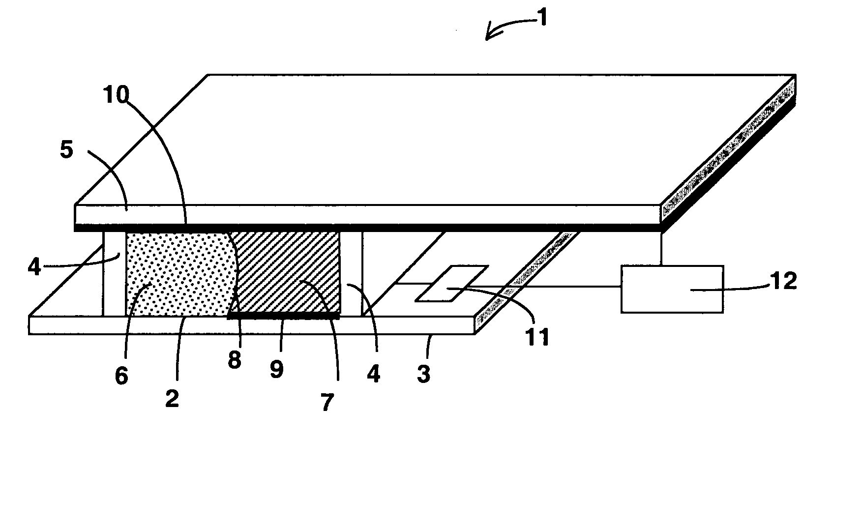
[0022]In FIG. 1, a microfluidic device 1, in particular used to perform extractions by solvent, comprises at least one microchannel bounded by a bottom wall 2 formed by a substrate 3, side walls 4 formed on the substrate and a top wall 5 parallel to the substrate. The microchannel is designed to bring a liquid and a fluid forming two phases 6 and 7 non-miscible with one another into contact. What is meant by a fluid is a liquid or a gas.

[0023]The microchannel is a hollow three-dimensional structure presenting a very great length with respect to the height. In the case where the length is very great with respect to the width, a microchannel of linear three-dimensional structure will be referred to. For example, the length of a microchannel is preferably about a few millimeters to a few centimeters, whereas the width and height are respectively about a few tens to a few hundreds of micrometers. The microchannel can also have a very great width with respect to its height, in particular...


PUM

PropertyMeasurementUnit
thicknessaaaaaaaaaa
lengthaaaaaaaaaa
widthaaaaaaaaaa

Abstract

The microfluidic device comprises at least one microchannel bounded by a bottom wall, side walls and a top wall and which is designed to contain at least one liquid and at least one fluid non-miscible with the liquid. The microfluidic device comprises means for stabilizing the interface between the liquid and the fluid. The means for stabilizing comprise at least one electrode arranged on at least one part of a first wall of the microchannel, over the entire length thereof, and at least one counter-electrode arranged over the entire length of the microchannel, on at least one part of a second wall, arranged facing the electrode. The electrode and counter-electrode are preferably respectively arranged on the bottom and top wall of the microchannel.

Description

[0001]This application is a 371 of PCT / FR03 / 03519, filed Nov. 27, 2003.BACKGROUND OF THE INVENTION[0002]The invention concerns a microfluidic device comprising at least one microchannel designed to contain at least one liquid and at least one fluid non-miscible with the liquid and means for stabilizing the interface between the liquid and the fluid, said microchannel being bounded by a bottom wall, side walls and a top wall.STATE OF THE ART[0003]Microlabs or microfluidic devices, better known as μ-TAS (micro Total Analysis System) or Lab-on-a-chip, are used to perform chemical or biological operations on samples of very small volumes. These volumes are for example of an order of magnitude comprised between a nanoliter and a microliter. It is thus known to use microfluidic devices to perform mixtures, separations, temperature checks, reactions or extractions by solvent.[0004]On this scale, one of the major difficulties arising from placing two phases non-miscible with one another in ...

Claims


Application Information

Patent Timeline
Patent Type & Authority Patents(United States)
IPC IPC(8): G01N27/453B01F13/00B01J19/00B01L3/00
CPCB01F13/0076B01F13/0093B01J19/0093B01L3/502776B01F2005/0031B01L2400/0415B01J2219/00853B01J2219/00889B01L2200/0636B01J2219/00783B01F2025/9171B01F33/3031B01F33/3039
Inventor SARRUT, NICOLAS
Owner COMMISSARIAT A LENERGIE ATOMIQUE ET AUX ENERGIES ALTERNATIVES
Why Eureka
Try Eureka