
Photographic document imaging system

a document imaging and document technology, applied in the field of photographic document imaging system, can solve the problems of image distortion, difficulty in image capture, and use of cameras, and achieve the effect of reducing the created distortion

Active Publication Date: 2009-09-22
COMPULINK MANAGEMENT CENT
View PDF46 Cites 61 Cited by
  • Summary
  • Abstract
  • Description
  • Claims
  • Application Information

AI Technical Summary

Benefits of technology

"The patent describes an apparatus and method for processing captured images of documents. The apparatus can use a stationary or non-stationary camera to capture the document. The method involves distinguishing the document from its background, adjusting the captured image to reduce distortions, and properly orienting the document. The technical effects of this patent include improved accuracy and efficiency in processing captured images of documents."

Problems solved by technology

However, the use of cameras creates difficulties in image capturing that do not exist when using a scanner.
In addition, use of a camera introduces image distortions, which may depend on various variables, such as the angle of the camera relative to the image, the lens used by the camera and its distance from the image, whether the image including a document is situated on a flat or curved surface and other factors.

Method used


Image

  • Photographic document imaging system
  • Photographic document imaging system
  • Photographic document imaging system

Examples


Embodiment Construction

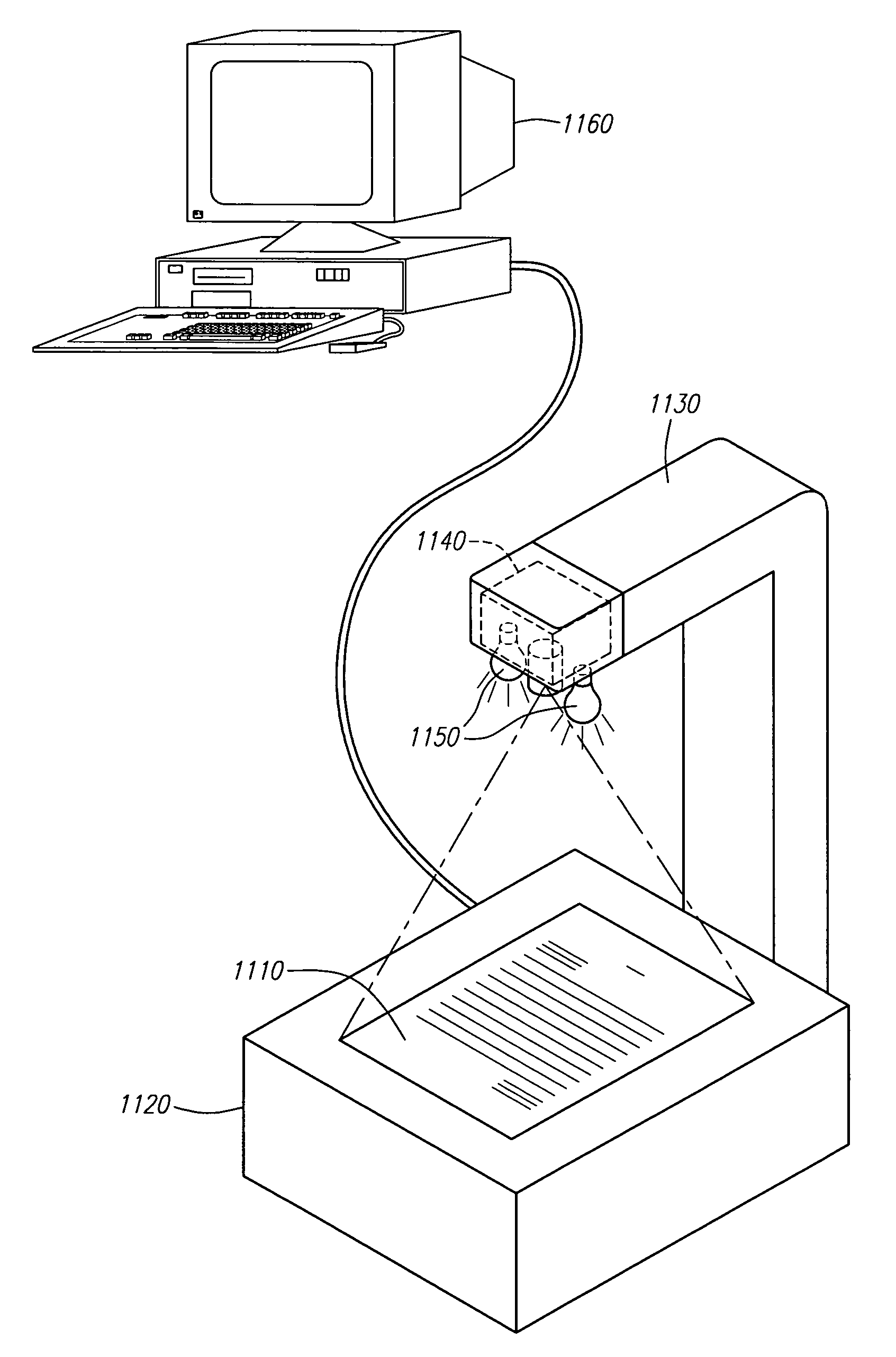
[0021]Embodiments described herein are operable to process an image captured from a camera that comprises a document. Embodiments described herein are operable to identify the captured document image from its background. After the captured document image is isolated from its background, embodiments described herein are operable to reduce or remove distortions of the captured document image. After the distortion of the captured document image is corrected, embodiments described herein are operable to rotate the captured document image to its proper orientation. Additionally, embodiments described herein provide the user with an evaluation of the success of implementing each of the steps in its various embodiments.

[0022]FIG. 2 depicts a general flowchart of a method for processing a captured image. After start 210, an image is received 220. The image may be received from various sources. For example, in one embodiment, the image may be received from a digital camera. In another embodi...


PUM


Abstract

An apparatus and method for processing a captured image and, more particularly, for processing a captured image comprising a document. In one embodiment, an apparatus comprising a camera to capture documents is described. In another embodiment, a method for processing a captured image that includes a document comprises the steps of distinguishing an imaged document from its background, adjusting the captured image to reduce distortions created from use of a camera and properly orienting the document is described.

Description

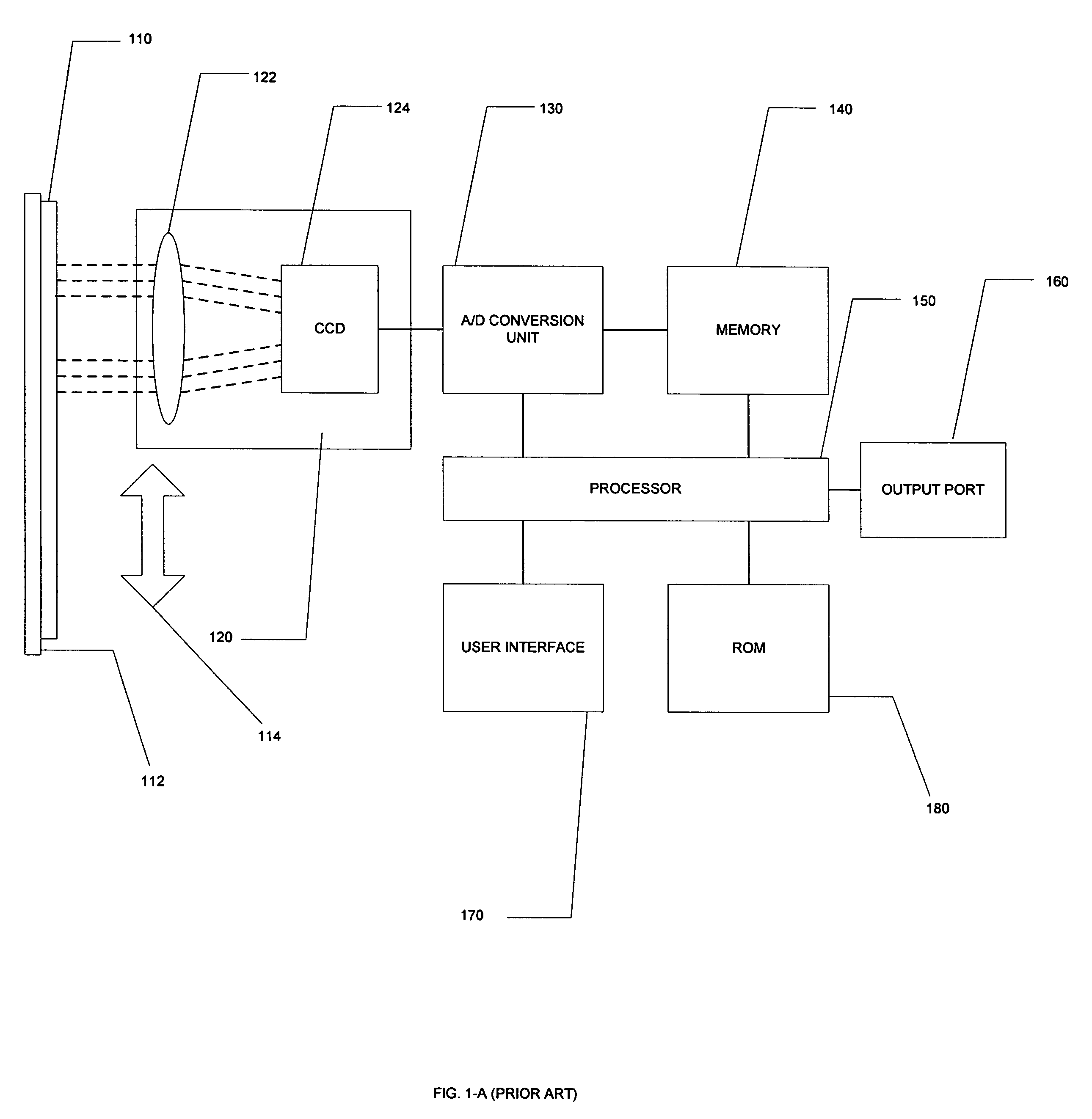
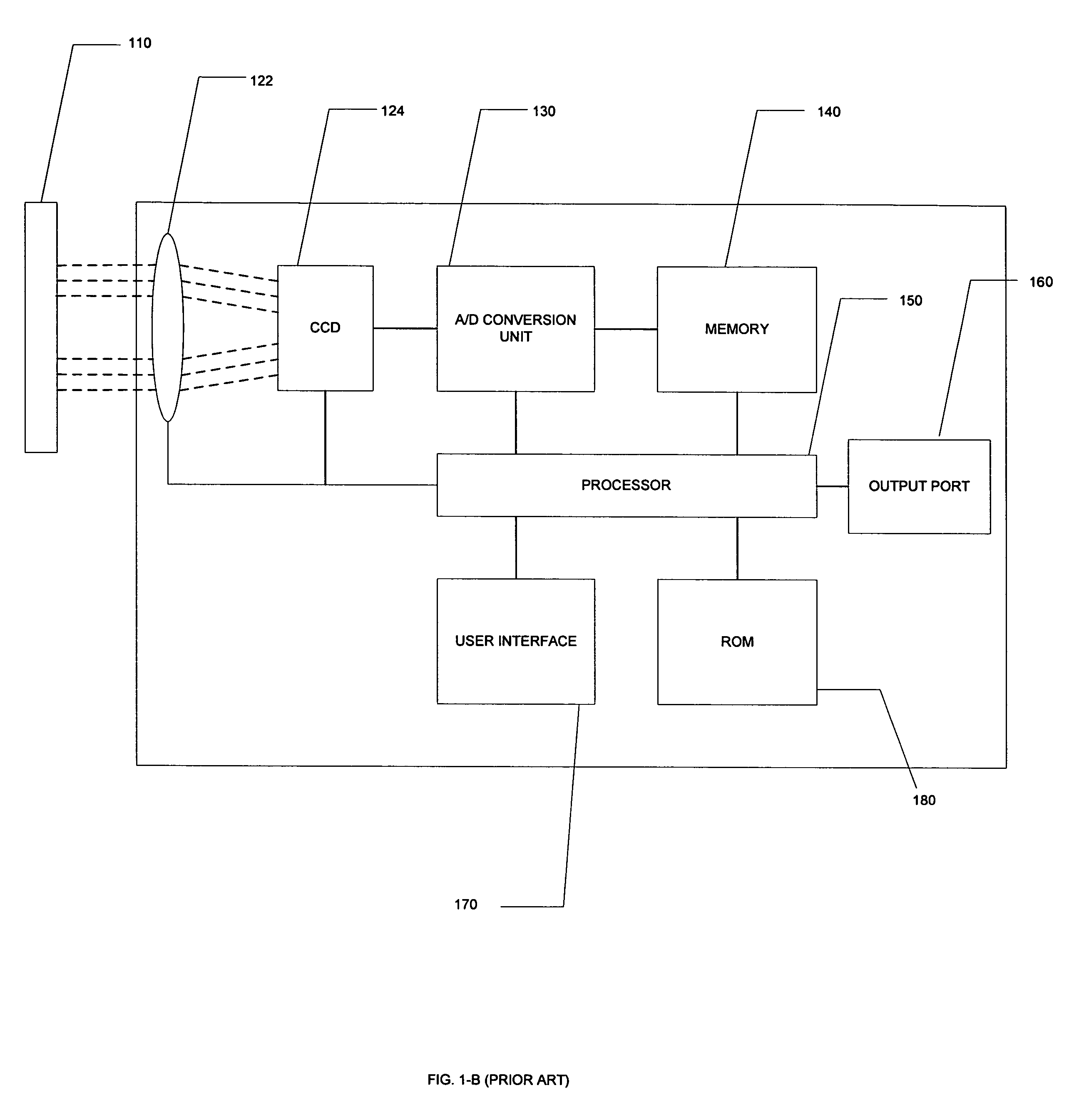
FIELD[0001]An apparatus and method for processing a captured image and, more particularly, for processing a captured image comprising a document.BACKGROUND[0002]FIG. 1-A is a block diagram depicting typical components of a scanner. A scanner is typically used to capture an image of a document 110. A document 110 is placed on the scanner plate 112. A scan head 120, which is generally comprised of an optical subsystem 122 and a charge-coupled device (“CCD”) 124, is moved across the document 110. Although FIG. 1A depicts only a two dimensional view, the scan head 120 may move across the document in both the direction illustrated by arrow 114 and in a direction orthogonal to the document 110. The optical subsystem 122 focuses light reflected from document 110 onto a CCD 124. CCD 124 is often implemented as a two-dimensional array of photosensitive capacitive elements. When light is incident on the photosensitive elements of the CCD 124, charge is trapped in a depletion region of the sem...

Claims


Application Information

Patent Timeline
Patent Type & Authority Patents(United States)
IPC IPC(8): G06K9/36G06V30/10H04N1/407
CPCG06K9/00449H04N1/3878G06K9/2063G06V30/412G06V30/10G06V30/1448G06T7/00G06V10/20
Inventor HEANEY, JR., EDWARD P.ANDREE, ZACHARYCLEGG, ZACHARIAHDARPINIAN, JAMESRAPELJE, KURT A.DODDS, ZACHARY
Owner COMPULINK MANAGEMENT CENT
Learn More