Contour measuring probe for measuring aspects of objects

a technology of measuring probes and contours, which is applied in the direction of measuring devices, mechanical measuring arrangements, instruments, etc., can solve the problems of large measurement errors, measurement errors, and measurement errors that are the difference between the design dimensions of the object and the actual dimensions of the manufactured obj

Active Publication Date: 2009-09-29
JIZHUN PRECISION IND HUIZHOU
View PDF9 Cites 2 Cited by
  • Summary
  • Abstract
  • Description
  • Claims
  • Application Information

AI Technical Summary

Benefits of technology

[0007]Nowadays, two methods are generally used to reduce a measuring force on the touch trigger probe. In a first method, the contact tip is obliquely arranged so that a component force of gravity acting on the measuring contact tip is regarded as a measuring force. The contact tip is very light, so the measuring force is very small accordingly. However, if an oblique angle of the contact tip changes during measuring, the measuring force will also change, which makes the measuring force difficult to control. In a second method, the touch trigger probe is configured with a spring. An elastic force of the spring is regarded as a measuring force. However, when the contact tip moves upward and downward along the surface of the object being measured, a vibration of the upward and downward movement may cause the spring to resonate and deform. Therefore, the measuring force varies with the deformation of the spring. Thus both methods are subjected to errors in the measurement results.

Problems solved by technology

Manufacturing errors are the differences between design dimensions of the object and actual dimensions of the manufactured object.
If the measuring force is too great, a measuring contact tip of the touch trigger probe may easily be damaged resulting in measuring errors.
If the measuring force is not steady, a relatively large measuring error may occur.
However, if the object has a slanted surface, the contact tip of the touch trigger probe may bend or deform by a counterforce acting on the touch trigger probe, thereby causing a measuring error.
Therefore, the touch trigger probe is not ideal for measuring precision lenses having slanted surfaces.
However, if an oblique angle of the contact tip changes during measuring, the measuring force will also change, which makes the measuring force difficult to control.
However, when the contact tip moves upward and downward along the surface of the object being measured, a vibration of the upward and downward movement may cause the spring to resonate and deform.
Thus both methods are subjected to errors in the measurement results.
Therefore, the air pump cannot provide a small, steady measuring force.

Method used


Image

  • Contour measuring probe for measuring aspects of objects
  • Contour measuring probe for measuring aspects of objects
  • Contour measuring probe for measuring aspects of objects

Examples


Embodiment Construction

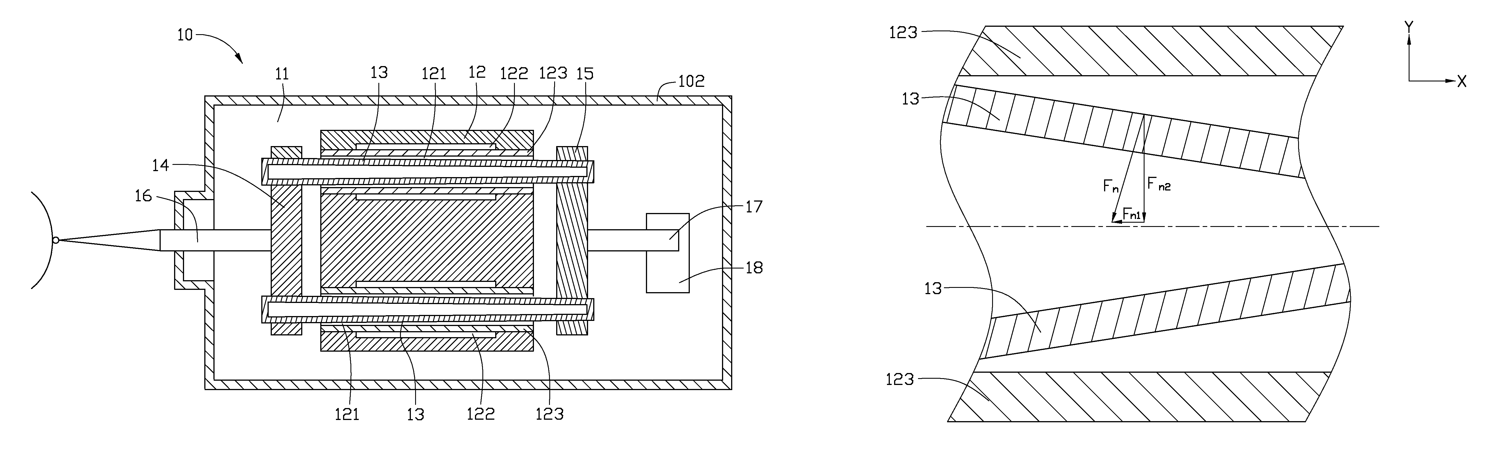
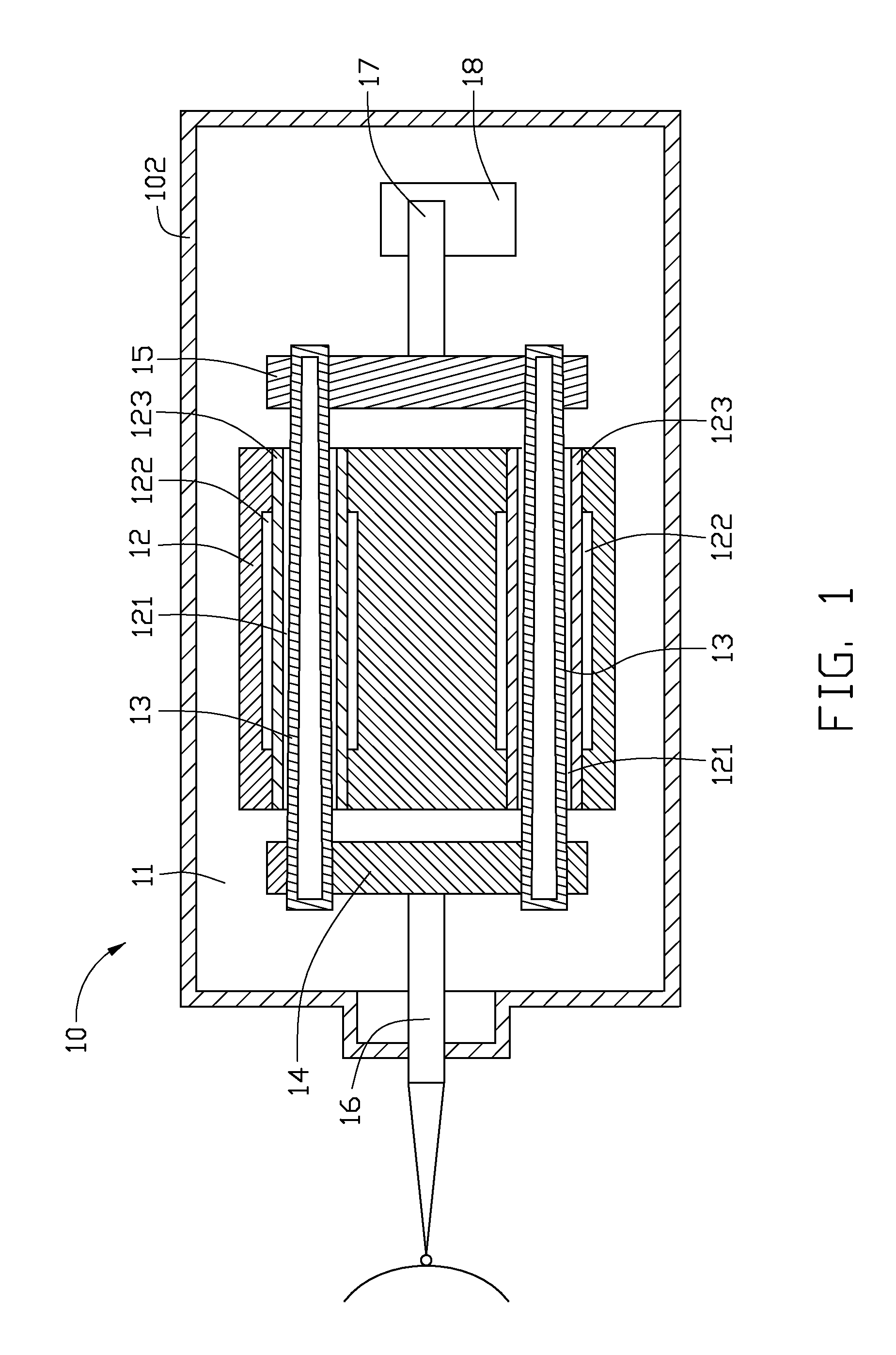
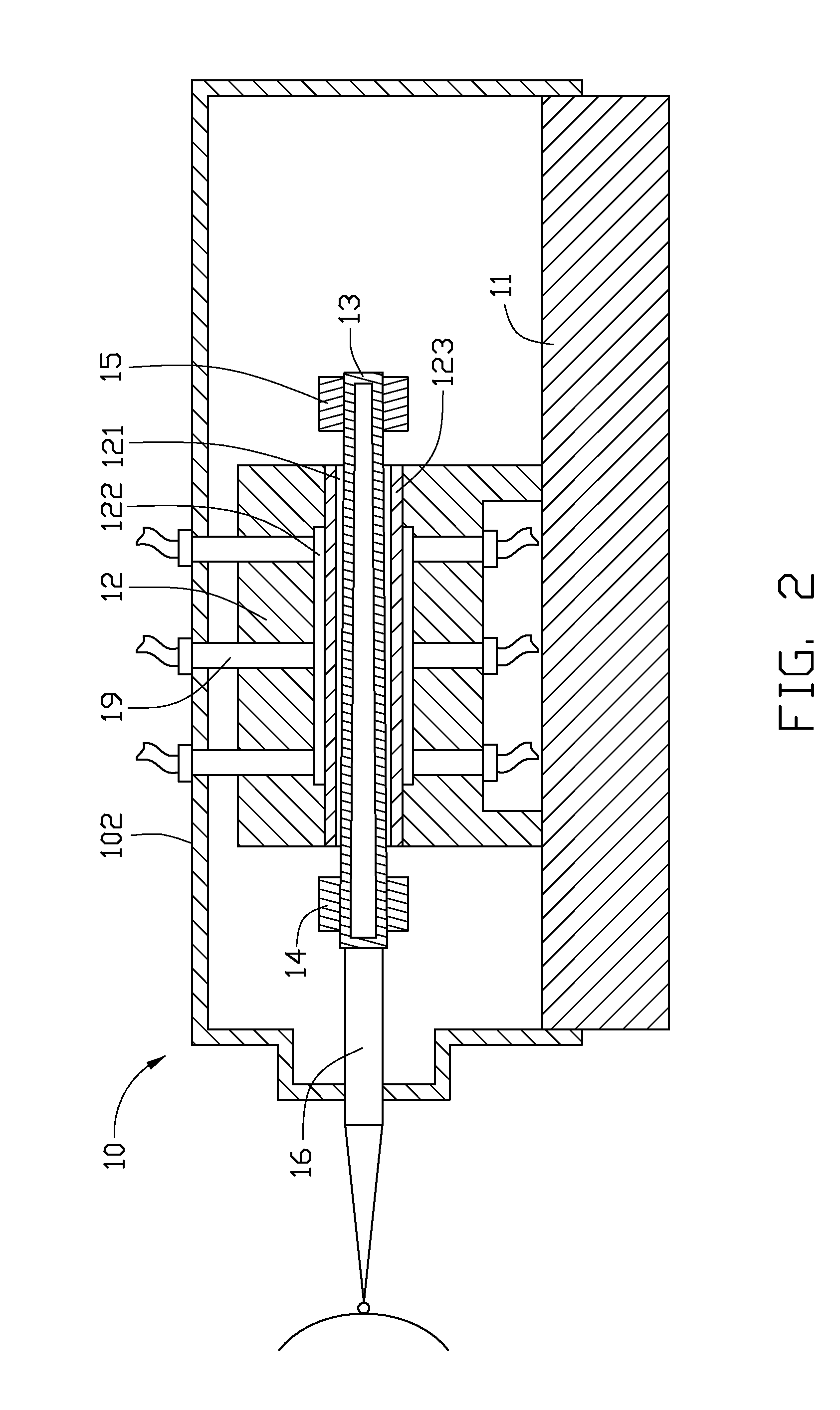
[0018]FIG. 1 and FIG. 2 shows a contour measuring probe 10 of a first embodiment of the present invention. The contour measuring probe 10 includes a base 11, a tube guide 12, two hollow tubes 13, a first fixing member 14, a second fixing member 15, a tip extension 16, a linear measuring scale 17, a displacement sensor 18, and a plurality of pipes 19.

[0019]The base 11 is substantially a flat rectangular sheet. It should be understood that the base 11 may alternatively be any other shapes. The tube guide 12 is securely mounted onto the base 11. The tube guide 12 includes a front end and a rear end. The tube guide 12 defines two tube chutes 121 extending from the front end to the rear end correspondingly. The tube chutes 121 are spaced apart from, and aligned parallel to, each other. A sidewall for defining each tube chute 121 defines a ring-shaped slot 122 communicating with the tube chutes 121. A porous film 123 is disposed inside each tube chute 121 of the tube guide 12 and between ...


PUM


Abstract

An exemplary contour measuring probe (10) includes a tip extension (16) and two driving members (13). The tip extension is configured for touching a surface of an object. The driving members are configured for driving the tip extension linearly moving along a first direction. The driving members are tapered and a diameter of each driving member increases along the first direction. The driving members are driven to move by gas pressure acting on an outer side surface thereof.

Description

CROSS-REFERENCE TO RELATED APPLICATIONS[0001]This application is related to nine co-pending U.S. patent applications, which are: application Ser. No. 11 / 611,724, filed on Dec. 15, 2006, and entitled “DISTANCE MEASURING PROBE WITH AIR DISCHARGE SYSTEM”, application Ser. No. 11 / 843,664, filed on Aug. 23, 2007, and entitled “CONTOUR MEASURING DEVICE WITH ERROR CORRECTING UNIT”, applications Ser. Nos. 11 / 966,951 and 11 / 966,952 and both entitled “CONTOUR MEASURING PROBE”, applications Ser. Nos. 11 / 966,957 and 11 / 966,956, and both entitled “CONTOUR MEASURING METHOD FOR MEASURING ASPECTS OF OBJECTS”, application Ser. No. 11 / 966,964, and entitled “MEASURING DEVICE FOR MEASURING ASPECTS OF OBJECTS”, application Ser. No. 11 / 966,961, and entitled “MEASURING DEVICE AND METHOD FOR USING THE SAME”, and application Ser. No. 11 / 966,959, and entitled “BASE AND CONTOUR MEASURING SYSTEM USING THE SAME”. In Ser. No. 11 / 611,724, Ser. Nos. 11 / 843,664 , 11 / 966,951 , 11 / 966,957, and 11 / 966,956, the invento...

Claims


Application Information

Patent Timeline
Patent Type & Authority Patents(United States)
IPC IPC(8): G01B5/012
CPCG01B5/20Y10S33/02
Inventor KONG, JIAN-BINLIU, QING
Owner JIZHUN PRECISION IND HUIZHOU
Why Eureka
Try Eureka