
Optical communications systems, devices, and methods

a technology of optical communication system and optical transmission channel, applied in the direction of multi-channel communication, digital transmission, electromagnetic transmission, etc., can solve the problems of limiting data transmission rate and distance, increasing system cost, and signal degrading

Inactive Publication Date: 2009-09-29
OPTIC153 LLC
View PDF10 Cites 54 Cited by
  • Summary
  • Abstract
  • Description
  • Claims
  • Application Information

AI Technical Summary

Benefits of technology

[0049]In another embodiment, the present invention includes an apparatus for performing one or more of the methods described herein.
[0050]Those and other embodiments of the present invention will be described in the following detailed description. The present invention addresses the needs described above in the description of the background of the invention by providing improved systems, apparatuses, and methods. These advantages and others will become apparent from the following detailed description.

Problems solved by technology

As the transmission rate of the data increase, chromatic and polarization mode dispersion (“PMD”) cause the signal to degrade thereby limiting data transmission rates and distances.
This increases the cost of the system and only allows for a fixed amount of compensation.
If the dispersion changes over time, it is difficult to change the amount of dispersion compensating fiber to compensate for the change.
Dispersion compensating fiber does not independently compensate for PMD.
One problem with this approach is that low dispersion fiber has a low dispersion characteristic only in a limited range of wavelengths, so in systems transmitting a large number of channels, the dispersion is low for only a small number of wavelengths.
Dispersion compensation fiber is expensive, and in many systems, existing fiber plants must be used.
Again, DCF is expensive.
Also, over time the dispersion characteristics of the system may change and this would require a changing the DCF used for compensation, which would be expensive and labor intensive.
In addition to the problems described above, low dispersion fiber and DCF do not correct of polarization mode dispersion.
One way to correct of for polarization mode dispersion is the carefully control the polarization of the optical signal, but the various methods for doing this are expensive and add complexity to the system.
It is easier and quicker to lock optical sources with low phase noise and less temperature sensitivity, but these types of optical sources are expensive.
Less expensive optical sources are available, but they have greater temperature sensitivity and phase noise making it more difficult to lock them to a specific wavelength using typical methods.
One problem with lower cost optical sources is phase noise.
Current methods of estimating optical source frequency and control take too much time to carry out and are corrupted by phase noise.

Method used


Image

  • Optical communications systems, devices, and methods
  • Optical communications systems, devices, and methods
  • Optical communications systems, devices, and methods

Examples


Embodiment Construction

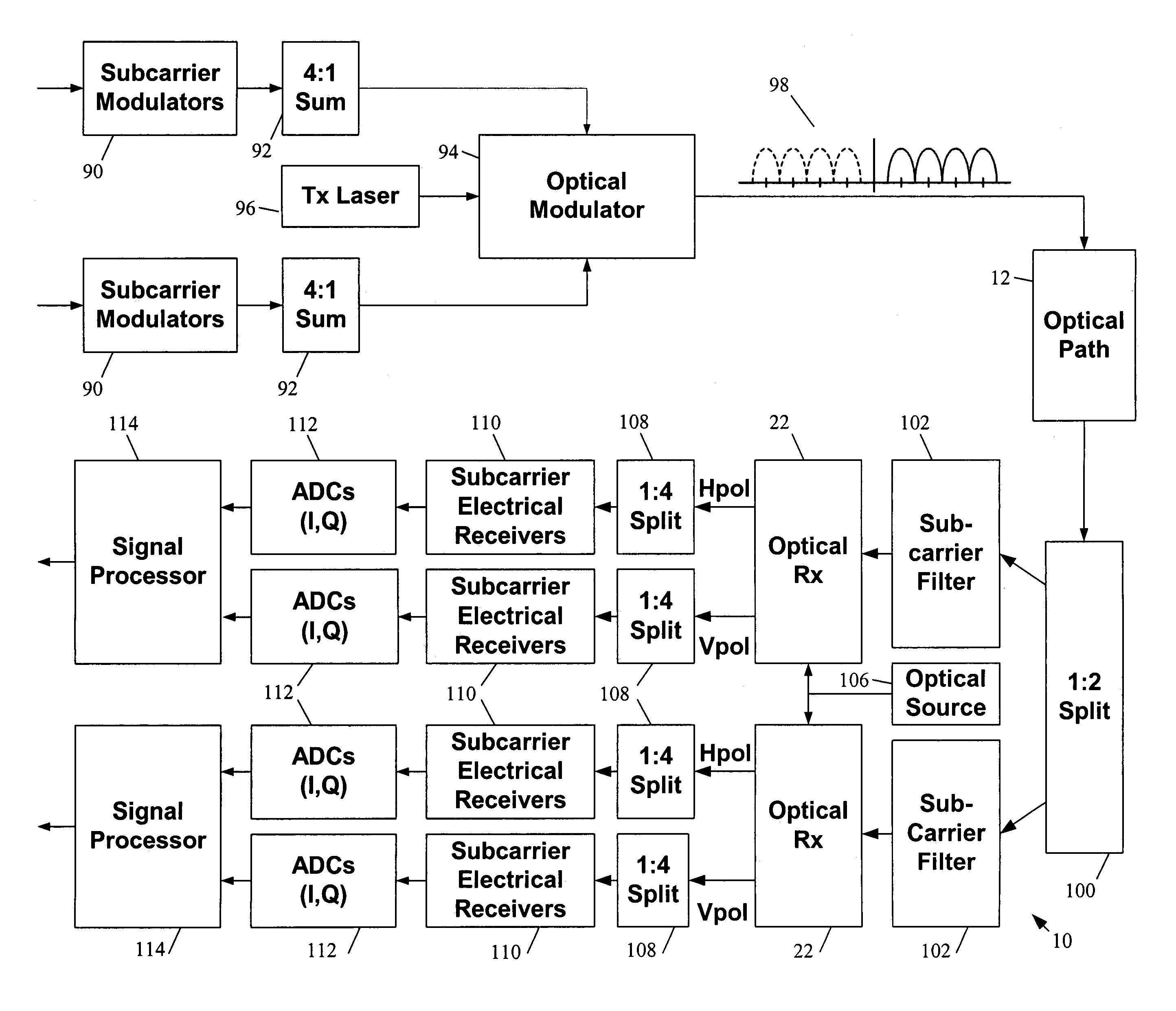
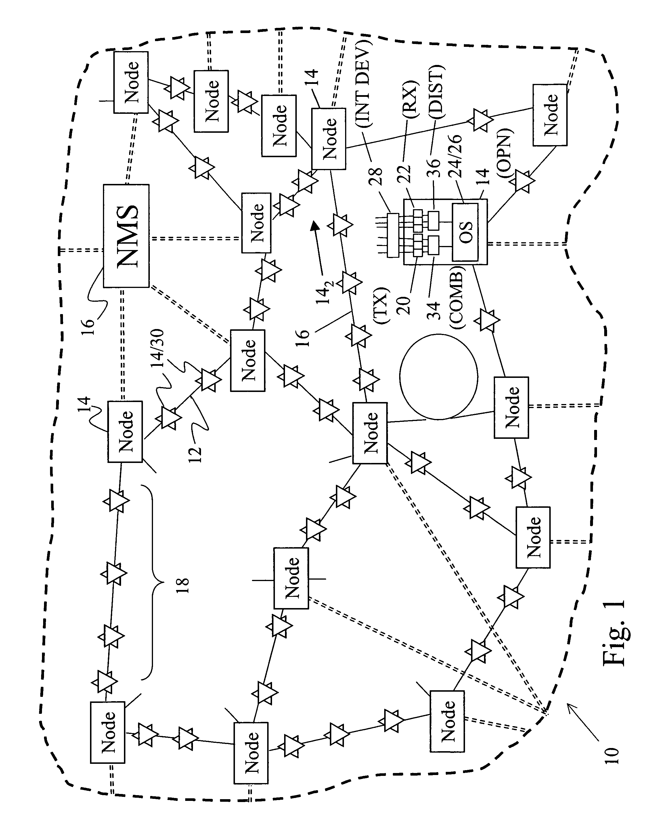
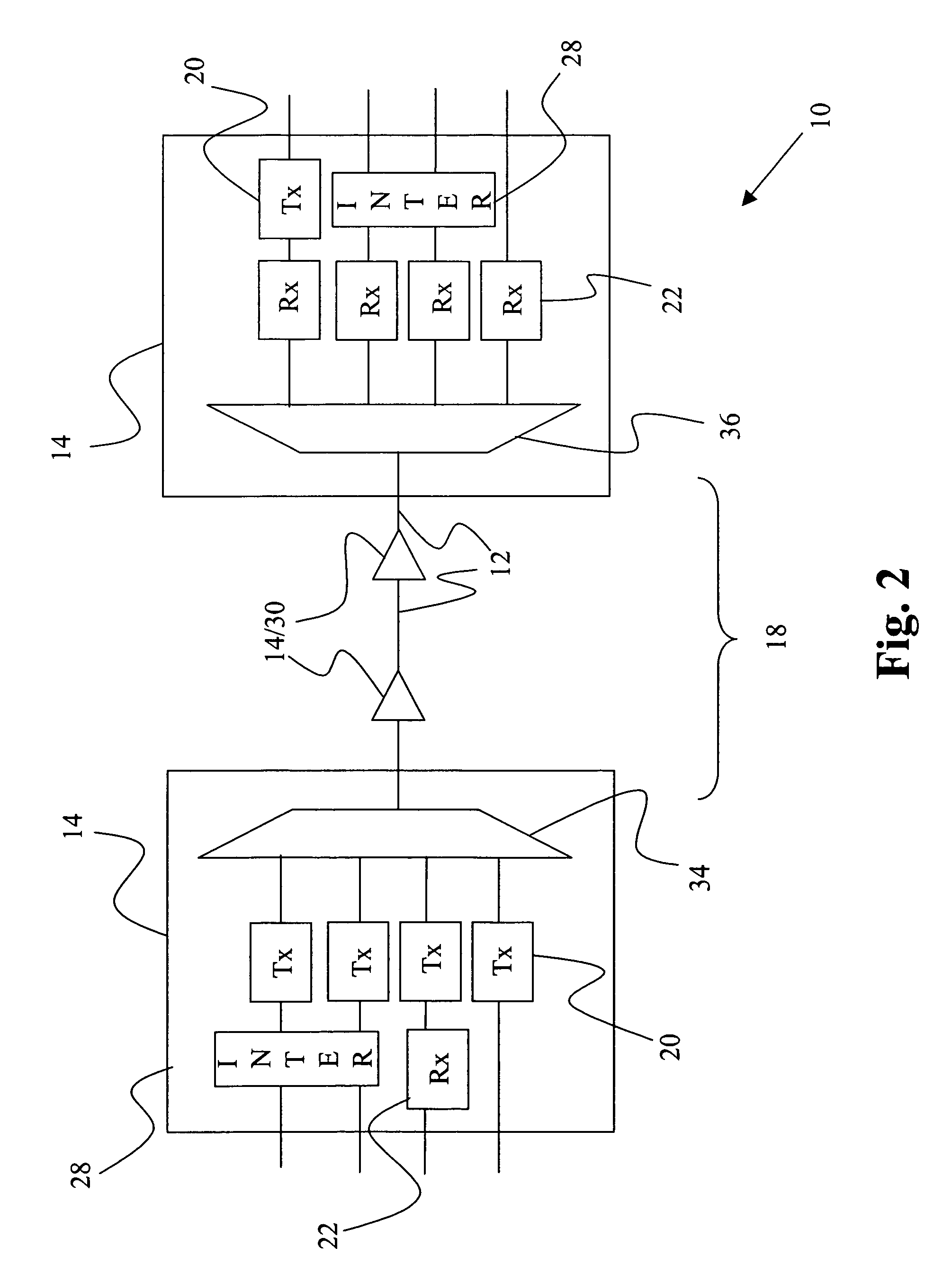
[0068]FIG. 1 illustrates an optical communications system 10 which includes optical paths 12 connecting nodes and network elements 14. Advantages of the present invention can be realized with many system 10 configurations and architectures, such as an all optical network, one or more point to point links, one or more rings, a mesh, other architectures, or combinations of architectures. The system 10 illustrated in FIG. 1 is a multi-dimensional network, which can be implemented, for example, as an all optical mesh network, as a collection of point to point links, or as a combination of architectures. The system 10 can employ various signal formats, and can also convert between formats. The system 10 can also include more or less features than those illustrated herein, such as by including or deleting a network management system (“NMS”) 16 and changing the number, location, content, configuration, and connection of nodes 14.

[0069]The optical paths 12 can include guided and unguided tr...


PUM


Abstract

A method and apparatus for estimating fiber dispersion in an optical communication system including transmitting an optical signal carrying a unique word along an optical communication path, receiving the optical signal carrying the unique word from the optical communication path, producing an electrical signal corresponding to the received unique word, and processing the electrical signal corresponding to the received unique word to produce an estimate of the fiber dispersion in the optical communication system.

Description

CROSS-REFERENCE TO RELATED APPLICATIONS[0001]This application is related to U.S. Provisional Patent Application Ser. No. 60 / 694,321, filed Jun. 27, 2005 and U.S. Provisional Patent Application Ser. No. 60 / 694,335, filed Jun. 27, 2005, and U.S. Provisional Patent Application Ser. No. 60 / 694,336, filed Jun. 27, 2005, all of which are incorporated herein by reference.STATEMENT REGARDING FEDERALLY SPONSORED RESEARCH OR DEVELOPMENT[0002]Not Applicable.BACKGROUND OF THE INVENTION[0003]The present invention is directed generally to the transmission of signals in optical communications systems. More particularly, the invention relates to systems, devices, and methods for dispersion compensation, for estimating and controlling the optical source frequency, and for estimating and controlling the optical source frequency in optical communication systems.[0004]The development of digital technology provided the ability to store and process vast amounts of information. While this development grea...

Claims


Application Information

Patent Timeline
Patent Type & Authority Patents(United States)
IPC IPC(8): H04B10/12H04J14/00
CPCH04B10/0775H04B10/07951H04L27/2096H04J14/0298H04B10/25133
Inventor PRICE, ALISTAIR J.BEIDAS, BASSEL F.BITTNER, TERRY L.HAMMONS, JR., A. ROGERKIRSCHNER, WILLIAM M.MCALISTER, DANIEL F.MUI, SHOU Y.
Owner OPTIC153 LLC
Learn More