
Impact test apparatus

a test apparatus and impact technology, applied in the direction of instruments, force/torque/work measurement apparatus, instruments, etc., can solve the problems of free oscillation of electronic apparatus such as mobile phone terminals, and the inability to examine the influence of free oscillation in the impact tes

Inactive Publication Date: 2009-10-06
FUJITSU LTD
View PDF11 Cites 7 Cited by
  • Summary
  • Abstract
  • Description
  • Claims
  • Application Information

AI Technical Summary

Benefits of technology

The present invention provides an impact test apparatus that can sufficiently reflect the influence of free oscillation. The apparatus includes a support, an elastic member, a retaining member, and a weight made to collide against the test object. The elasticity of the elastic member allows the retaining member to retain the test object while the weight collides with it, resulting in impact. The test object is then subjected to free oscillation in response to the impact. The apparatus minimizes damping of the free oscillation and allows for sufficient realization of the movement of the test object. The apparatus can be designed to have a small allowable distance between the retaining member and the test object, ensuring accurate results.

Problems solved by technology

In general, an electronic apparatus such as a mobile phone terminal suffers from free oscillation after the application of impact of a fall.
It is thus impossible to examine the influence of the free oscillation in the impact test.

Method used


Image

  • Impact test apparatus
  • Impact test apparatus
  • Impact test apparatus

Examples


first embodiment

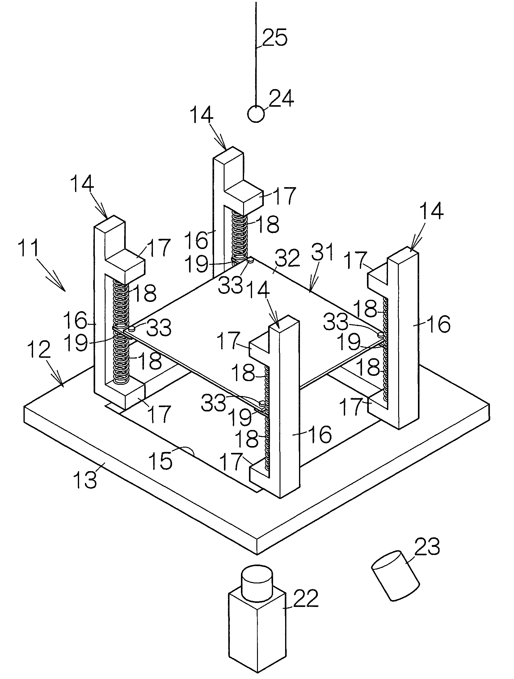
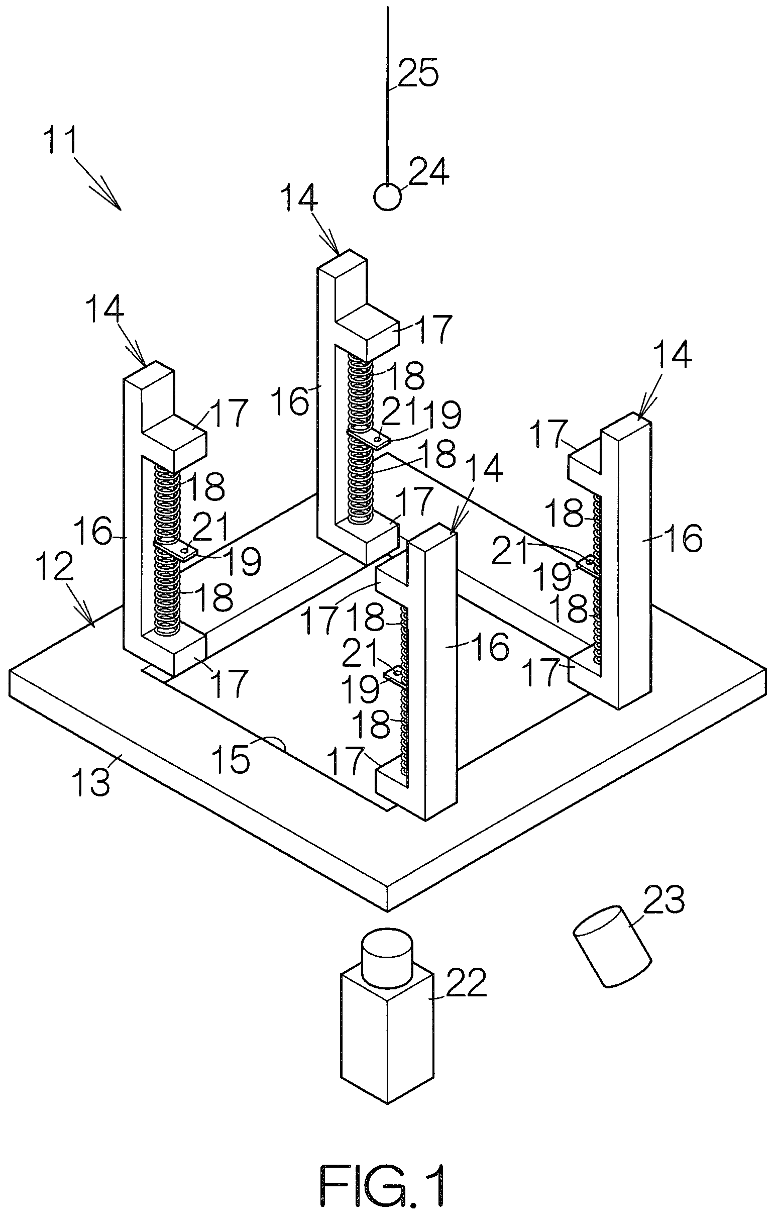
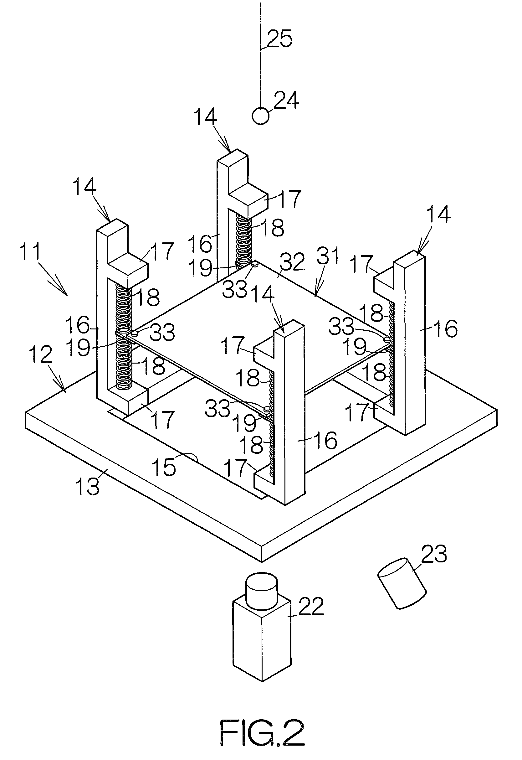
[0019]FIG. 1 schematically illustrates an impact test apparatus 11 according to the present invention. The impact test apparatus 11 includes a support 12. The support 12 includes a base 13 extending along the horizontal plane, and four support posts 14 standing upright from the base 13, for example. A window opening 15 is defined in the base 13. The base 13 is immobilized on a support table, not shown, for example. The base 13 may be made of a metallic material such as aluminum, for example.

[0020]The support posts 14 are fixed to the base 13. The individual support posts 14 include a main elongated body 16 standing upright from the base 13 and a pair of upper and lower protrusions 17, 17 protruding from the main body 16. The upper and lower protrusions 17, 17 are spaced from each other at a predetermined interval in the vertical direction. The upper and lower protrusions 17 may be formed integral with the main body 16. The upper and lower protrusions 17 protrude from the support pos...

second embodiment

[0039]FIG. 4 schematically illustrates an impact test apparatus 11a according to the present invention. The impact test apparatus 11a utilizes a support 12a including four support posts 41 fixed to the base 13, for example. The individual support posts 41 have an L-shaped cross-section. The inner surfaces of the four support posts 41, 41, . . . are positioned to contour a space of a parallelepiped standing upright on the base 13. The support posts 41 may be made of a metallic material such as aluminum, for example.

[0040]A pair of upper and lower first magnets 42, 42 are fixed to the inner surfaces of the individual support posts 41. An adhesive or a screw may be employed to fix the first magnets 42, for example. The upper and lower first magnets 42, 42 are spaced from each other at a predetermined interval in the vertical direction. A second magnet 43 is placed in a space between the upper and lower first magnets 42, 42. The aforementioned retaining member 19 is attached to the seco...


PUM

PropertyMeasurementUnit
heightaaaaaaaaaa
weightaaaaaaaaaa
distanceaaaaaaaaaa

Abstract

An impact test apparatus allows a retaining member to retain a test object. The retaining member is attached to an elastic member. When a weight is made to collide against the test object, impact is applied to the test object. The test object is subjected to free oscillation in response to the impact. The elasticity of the elastic member accepts the movement of the retaining member. Damping of the free oscillation of the test object is minimized. The impact test sufficiently reflects the influence of the free oscillation.

Description

BACKGROUND OF THE INVENTION[0001]1. Field of the Invention[0002]The present invention relates to an impact test apparatus allowing a weight to collide against a test object for testing or measuring the strength of the test object, for example.[0003]2. Description of the Prior Art[0004]Solder bumps are employed to bond a large-scale integrated (LSI) circuit package and a printed wiring board. The solder bumps are arranged to establish a so-called ball grid array (BGA), for example. An impact test is executed so as to evaluate the bonding strength of the ball grid array. Four corners of the printed wiring board are fixed to a support for the impact test. A weight is made to collide against the printed wiring board. Subsequently, electric connection is examined between the printed wiring board and the LSI package.[0005]In general, an electronic apparatus such as a mobile phone terminal suffers from free oscillation after the application of impact of a fall. According to an observation ...

Claims


Application Information

Patent Timeline
Patent Type & Authority Patents(United States)
IPC IPC(8): G01N3/56
CPCG01N3/303G01N2203/0033G01N2203/001
Inventor IDO, OSAMU
Owner FUJITSU LTD
Learn More